Introduction
As bandwidth demands rise from AI, cloud, and high-performance workloads, data centers need fiber infrastructure that delivers more connections without consuming more rack space. A fiber optic distribution panel built for high-density MPO/MTP cabling helps consolidate terminations, simplify cross-connects, and support faster migration to 40G, 100G, and beyond. It also improves cable management and reduces the risk of congestion as networks scale. The following discussion explains how these panels strengthen efficiency, preserve signal performance, and create a practical path for expanding capacity within existing physical limits.
High-Density MPO/MTP in Fiber Distribution
As enterprise and hyperscale data centers scale to meet unprecedented bandwidth demands, the physical layer infrastructure faces immense pressure to maximize space utilization while maintaining flawless signal integrity. The Fiber Optic Distribution Panel serves as the critical nerve center in this environment, managing the complex routing of high-speed optical connections between core routers, spine switches, and leaf servers. Transitioning from legacy duplex setups to high-density MPO (Multi-Fiber Push On) and MTP (Mechanical Transfer Push-on) solutions represents a fundamental shift in optical architecture. This evolution enables facilities to achieve massive scalability and port density without expanding their physical footprint, effectively decoupling bandwidth growth from real estate constraints. Furthermore, the strategic deployment of these high-density panels dictates the facility's ability to seamlessly support both multimode (OM4/OM5) applications for short-reach intra-rack connections and single-mode (OS2) fiber for long-reach inter-building data center interconnects (DCI).
Capacity growth, AI workloads, and speed migration
The proliferation of artificial intelligence (AI), machine learning (ML) training clusters, and high-performance computing (HPC) has fundamentally altered data center traffic patterns. East-West traffic now dominates, necessitating flattened leaf-spine architectures that require intensely dense optical interconnects. To support the migration from 100G to 400G and the emerging 800G Ethernet standards, parallel optics have become a mandatory architectural standard. AI workloads, operating on highly synchronized parallel processing algorithms, are exceptionally sensitive to latency and packet loss, demanding optical links with transmission delays tightly controlled well below 1 microsecond. Consequently, facilities are migrating rapidly toward Base-8 and Base-16 MPO configurations. These architectures align perfectly with the octal nature of QSFP-DD and OSFP transceivers (transmitting 4x100G or 8x100G lanes), ensuring 100% fiber utilization without the stranded dark fibers that plague legacy Base-12 deployments in modern high-speed fabrics. For instance, while an OM4 multimode deployment might cap out at 100 meters for 400G SR8, migrating the panel infrastructure to OS2 single-mode parallel optics allows the same footprint to support 500-meter to 2-kilometer reaches required by hyperscale campuses.
Core elements of high-density MPO/MTP architecture
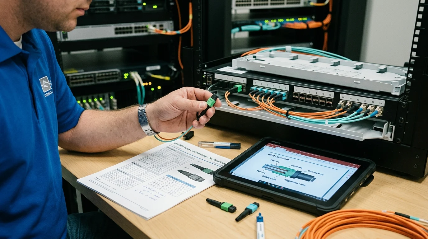
A high-density MPO/MTP architecture relies on several meticulously engineered components working in concert within the Fiber Optic Distribution Panel. The primary building blocks include pre-terminated MPO trunk cables, MPO-to-LC transition cassettes, and highly modular rack-mount enclosures. Modern high-density panels are engineered to support anywhere from 144 to 288 LC fibers, or up to 864 MPO fibers, within a single Rack Unit (1RU) space. This extreme volumetric density is achieved through staggered port alignments, sliding tray mechanisms, and advanced micro-cable technologies that reduce trunk diameters by up to 30% compared to traditional loose-tube designs. The MTP connector itself—a high-performance iteration of the standard MPO—features a floating ferrule and precision elliptical guide pins. These mechanical enhancements critically reduce wear and maintain exact physical contact across all 12, 16, or 24 fibers during repeated mating cycles. Maintaining precise physical contact is a non-negotiable requirement when managing multi-terabit optical throughput in a highly confined chassis, as even microscopic air gaps can cause severe signal degradation and catastrophic link failure.
Technical Criteria for MPO/MTP Integration
Integrating a high-density Fiber Optic Distribution Panel requires meticulous evaluation of both optical and mechanical specifications. Network architects must continuously balance the physical constraints of the rack environment with the stringent optical budgets dictated by next-generation IEEE networking standards.
Fiber count, insertion loss, and polarity
The selection of fiber count, insertion loss (IL), and polarity methodology forms the technical foundation of any successful MPO deployment. While standard-loss MPO connectors typically specify a maximum insertion loss of 0.75 dB, advanced ultra-low loss (ULL) MTP connectors guarantee an IL of 0.35 dB or even 0.20 dB per mated pair. This distinction is absolutely critical for 400GBASE-DR4 and 800GBASE-DR8 links, which impose strict end-to-end channel loss budgets—often limited to a mere 3.0 dB or 4.0 dB over a 500-meter span of single-mode fiber. Polarity management, the science of ensuring the transmit signal correctly routes to the corresponding receive port, is equally vital. The TIA-568 standard defines Methods A, B, and C. Method B, which utilizes key-up to key-up MPO adapters and straight-through trunk cables, has emerged as the definitive preferred choice for high-density parallel optics. Method B provides superior scalability and simplifies patch cord management by utilizing identical Type B patch cords at both ends of the link, eliminating the administrative overhead of stocking multiple patch cord variants.
MPO vs LC deployment comparison
The transition from traditional LC duplex networks to parallel MPO architectures involves significant operational and spatial shifts. While LC connectors offer familiarity and simplicity for legacy 10G/25G links, they severely bottleneck port density at the panel level.
| Feature/Metric | Duplex LC Deployment | High-Density MPO/MTP Deployment |
|---|---|---|
| Maximum Density (per 1RU) | 144 fibers (72 ports) | Up to 864 fibers (using 24-fiber MPOs) |
| Deployment Speed | Slow (individual field patching) | Rapid (plug-and-play factory trunks) |
| Future Migration Path | Requires complete recabling for >100G | Supports native parallel optics (400G/800G) |
| Cable Bulk & Weight | High (restricts rack cooling airflow) | Low (micro-distribution trunk cables) |
| Insertion Loss (per mate) | ~0.15 dB to 0.25 dB | ~0.20 dB to 0.35 dB (ULL MTP components) |
By consolidating multiple optical pathways into a single physical interface, an MPO-based Fiber Optic Distribution Panel drastically reduces cable bulk. This consolidation accelerates initial deployment times by up to 75% compared to field-terminated or individually patched LC environments, while simultaneously freeing up critical pathway space in overhead trays and under-floor routing channels.
Airflow, bend radius, labeling, and access
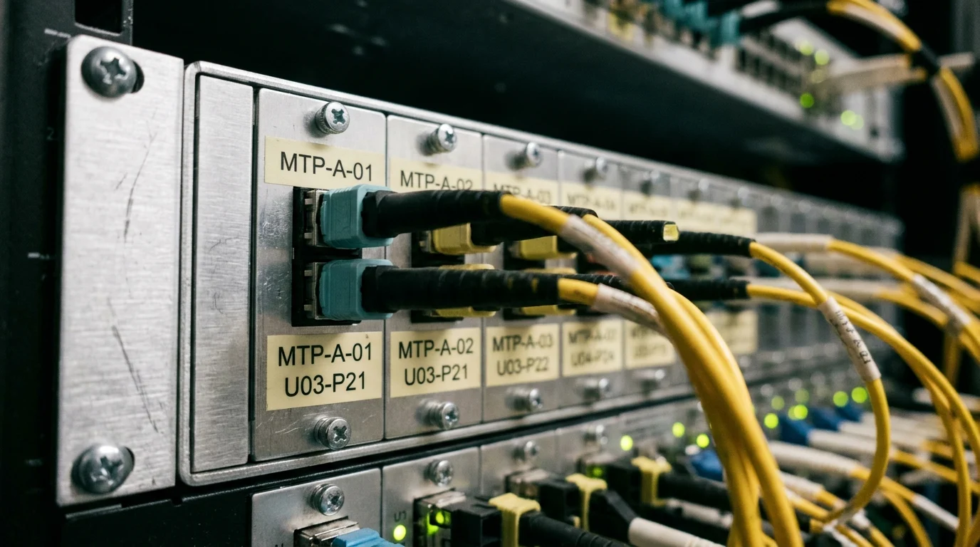
Beyond pure optical performance, the mechanical integration of the Fiber Optic Distribution Panel dictates the long-term reliability of the network. Extreme density can severely impede cooling airflow within the server cabinet, leading to thermal throttling of active network equipment and increased cooling costs. Modern panels mitigate this through optimized internal cable routing channels and ultra-slim profile cassette designs that promote front-to-back airflow containment strategies. Bend radius protection is enforced using bend-insensitive fiber (BIF) compliant with ITU-T G.657.A2 standards for single-mode applications, which permits a minimum bend radius of just 7.5 millimeters without inducing performance-degrading macrobend attenuation. Furthermore, rigorous labeling schemes compliant with TIA-606-C and tool-less front/rear access mechanisms are mandatory design features. These elements prevent accidental disconnections and fiber damage during routine MACs (Moves, Adds, and Changes) in tightly packed 1RU and 4RU distribution chassis.
Performance, Compliance, and Lifecycle Cost
The financial and operational viability of a high-density Fiber Optic Distribution Panel deployment hinges on a rigorous analysis of lifecycle costs, regulatory compliance, and verified optical performance. Capital expenditure (CAPEX) on premium optical components must be firmly justified by operational expenditure (OPEX) savings, reduced downtime, and deferred infrastructure upgrade costs over the facility's lifespan.
Low-loss components vs budget trade-offs
Network designers frequently face challenging trade-offs between initial component cost and long-term optical headroom. Ultra-low loss (ULL) MTP cassettes and trunk cables typically command a price premium of 30% to 40% over their standard-loss equivalents. However, investing in ULL components within the Fiber Optic Distribution Panel provides essential insurance for the overall optical budget. For example, a complex multi-hop data center link might require four or five cassette transitions between the spine and the edge. Using standard 0.75 dB loss cassettes, a four-hop link incurs 3.0 dB of connection loss alone, instantly failing the strict IEEE 802.3bs loss budget for a 400G DR4 circuit. Conversely, utilizing 0.35 dB ULL cassettes reduces that connection loss to a highly manageable 1.4 dB, preserving the remaining budget for inherent cable attenuation and future aging margins. This critical performance buffer prevents the extremely costly requirement of deploying signal regenerators or expensive Active Optical Cables (AOCs) as the network scales physically outward.
Standards, testing, and documentation
Strict adherence to international telecommunications standards ensures interoperability, physical safety, and long-term signal reliability. High-density MPO solutions must fully comply with TIA-568.3-D for optical fiber cabling components and IEC 61754-7 for MPO connector interface geometries. Comprehensive quality assurance protocols demand 100% factory testing of pre-terminated assemblies. This includes mandatory 3D interferometry to verify precise ferrule geometry, specifically measuring the radius of curvature, apex offset, and exact fiber height. Furthermore, strict compliance with IEC 61300-3-35 for end-face inspection guarantees that distribution panels arrive entirely free of microscopic defects, scratches, or contamination. Return Loss (RL) is heavily scrutinized in high-speed environments; single-mode MPO/APC (Angled Physical Contact) connectors must consistently achieve an RL of <-60 dB to prevent detrimental back-reflections from degrading the performance of highly sensitive PAM4 transceivers used in modern AI fabric networks. Comprehensive documentation, including serialized, downloadable test reports for every single trunk and cassette, is a mandatory deliverable for tier-1 infrastructure validation and troubleshooting.
Deployment, Migration, and Supplier Selection
Successfully upgrading to a high-density Fiber Optic Distribution Panel requires strategic logistical planning, phased execution, and rigorous vetting of component manufacturers. The migration path must be designed to minimize active network downtime while establishing a highly robust physical foundation for future scaling initiatives.
Planning and implementation sequence
The implementation sequence for a high-density rollout is typically divided into Day 0 (design, surveying, and procurement), Day 1 (physical installation), and Day 2 (operations, MACs, and scaling). During Day 0, precise measurement of cable pathways is absolutely critical, as pre-terminated MPO trunks are custom-manufactured to exact lengths and cannot be spliced or altered in the field without destroying their optical properties. Procurement planning must account for standard industry lead times, which typically range from 4 to 8 weeks for custom, high-fiber-count assemblies such as 144-fiber or 288-fiber trunks. Day 1 execution focuses on racking the Fiber Optic Distribution Panel, carefully pulling the trunks through overhead ladder racks or sub-floor trays, and snapping the MTP connectors into the rear of the modular cassettes. This streamlined plug-and-play architecture drastically reduces installation windows from several weeks to mere days, provided the pathway routing adheres strictly to maximum fill ratios (typically capped at 40% for new installations) to avoid crushing the delicate micro-cables under their own weight.
How to evaluate suppliers
Selecting an infrastructure partner extends far beyond evaluating basic unit pricing; it requires a comprehensive audit of the supplier's manufacturing capabilities, quality control processes, and supply chain resilience. Tier-1 suppliers exclusively source raw optical glass from leading global manufacturers to ensure uniform refractive indices and minimal core eccentricity across all fiber strands. Evaluators should demand concrete evidence of ISO 9001 certification and request anonymized first-pass yield (FPY) data for their MTP termination production lines. A reputable, enterprise-grade supplier should consistently demonstrate an FPY exceeding 98% for complex multi-fiber assemblies. Additionally, the availability of localized technical support, rapid field engineering services, and transparent, long-term warranty policies (often extending 15 to 25 years for passive optical networks) are critical differentiators when evaluating vendors for mission-critical hyperscale deployments.
Decision matrix for panel selection
The final panel selection involves weighing multiple architectural variables against the facility's specific operational model and budget constraints.
| Evaluation Criteria | Base-Level Panel | Premium High-Density Panel | Weighting for AI/HPC |
|---|---|---|---|
| Port Density | Up to 72 LC / 1RU | 144+ LC or 864 MPO / 1RU | Critical (High) |
| Chassis Modularity | Fixed bulkheads | Mix-and-match Base-8/12/16 cassettes | High |
| Cable Management | Static routing rings | Sliding trays, articulated strain relief | High |
| Material Construction | Standard cold-rolled steel | Lightweight aluminum, tool-less latches | Medium |
| Lifecycle Cost Multiplier | 1.0x (Baseline CAPEX) | 1.5x – 2.5x (Lower OPEX) | Medium (CAPEX vs OPEX) |
Utilizing a structured decision matrix ensures the chosen Fiber Optic Distribution Panel directly aligns with the data center's 5-year technology roadmap. Facilities anticipating rapid, successive generation shifts in switch silicon should heavily weight modularity and sliding-tray accessibility over the initial chassis procurement cost, as the labor savings during future upgrades will rapidly offset the premium hardware investment.
Long-Term Fiber Distribution Panel Decisions
Future-proofing the physical layer is the ultimate objective when a data center standardizes on a specific Fiber Optic Distribution Panel ecosystem. As the telecommunications industry looks toward the next decade of networking, the physical infrastructure deployed today must seamlessly support impending multi-terabit optical standards without requiring highly disruptive and costly rip-and-replace operations.
Density, serviceability, and upgrade readiness
The inevitable transition to 1.6T and 3.2T Ethernet architectures will push port densities and core fiber counts to unprecedented levels within the rack. Future-ready Fiber Optic Distribution Panels are already evolving to support Very Small Form Factor (VSFF) connectors, such as the SN and MDC interfaces, which effectively triple the density of standard LC interfaces directly at the patch panel bulkhead. In ultra-high-density configurations, modern 1RU chassis are being meticulously engineered to accommodate up to 576 discrete fibers utilizing these advanced interfaces alongside high-lane-count Base-16 MPO trunks. However, as volumetric density increases, serviceability remains a paramount concern. The ability for technicians to access, clean, or replace a single failing patch cord without disturbing or disconnecting adjacent active links is a strict operational mandate in high-uptime environments. Advanced panels incorporate automated RFID port mapping and highly articulated sliding trays, which demonstrably reduce Mean Time To Repair (MTTR) by up to 40% during localized link failures. Upgrade readiness is primarily achieved through deep chassis modularity, allowing network operators to efficiently swap out legacy Base-12 MPO-to-LC cassettes for newer Base-8 or Base-16 MPO pass-through adapter plates as the active switching equipment is upgraded to native parallel optics. Ultimately, treating the Fiber Optic Distribution Panel not as a static metal box, but as a dynamic, highly engineered physical interface platform, guarantees that the passive optical network remains a powerful enabler of technological advancement rather than a restrictive bottleneck to future capacity growth.
Key Takeaways
- The most important conclusions and rationale for Fiber Optic Distribution Panel
- Specs, compliance, and risk checks worth validating before you commit
- Practical next steps and caveats readers can apply immediately
Frequently Asked Questions
What is the main benefit of using high-density MPO/MTP in a fiber optic distribution panel?
It increases port density and bandwidth in the same rack space, helping data centers scale 100G, 400G, and 800G links without expanding footprint.
When should I choose Base-8 or Base-16 instead of Base-12 MPO?
Choose Base-8 or Base-16 for modern 400G/800G parallel optics. They match QSFP-DD and OSFP lane structures better and reduce unused stranded fibers.
How do MPO/MTP panels support both multimode and single-mode networks?
Use OM4/OM5 for short intra-rack or row links, and OS2 for longer campus or inter-building runs. The panel can be configured with modules and trunks for either type.
What should I check first when selecting an MPO/MTP fiber distribution panel?
Verify fiber count, insertion loss, polarity method, and rack density. Also confirm compatibility with your target transceivers, such as 400G SR8 or single-mode parallel optics.
Why is low insertion loss so important in high-density MPO/MTP deployments?
High-speed links have tight optical budgets. Lower insertion loss preserves signal margin, improves link reliability, and reduces risk of errors across multiple connectors and cassettes.