


Understanding the Fundamentals: What Does an Optical Power Meter Measure?
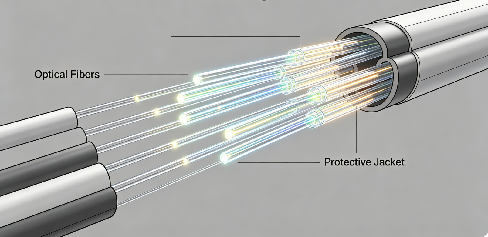
An optical power meter (OPM) primarily measures the intensity or “brightness” of light exiting a fiber optic cable, expressed in either Milliwatts (mW) or Decibels (dBm). This instrument serves as the fundamental tool for verifying that optical signals are strong enough to be detected by a receiver after traveling through a network. By converting light energy into an electrical current through a calibrated photodiode, the OPM provides a precise reading of the power level within a specific fiber link.
Effective fiber testing requires a high degree of accuracy to prevent signal degradation. According to the Telecommunications Industry Association (TIA), maintaining precise power levels is essential for the long-term reliability of high-speed data centers and telecommunications infrastructure. In modern applications, such as those utilizing MPO/MTP Solutions, an optical power meter is indispensable for validating the integrity of high-density trunk cables before they are commissioned for active traffic.
Core Measurements and Units
Optical power meters typically provide two distinct types of measurements that are essential for different stages of the fiber testing lifecycle:
- Absolute Power (dBm/mW): This measurement reflects the current amount of optical power being transmitted through the fiber. It is most commonly used to check the output of a source, such as a Fiber Optic Transceiver Module, to ensure it meets the manufacturer’s specified output range.
- Relative Power or Insertion Loss (dB): This is a calculated value representing the difference between the power entering a fiber and the power exiting it. It is the primary metric used to determine if the fiber, connectors, and splices are causing excessive signal attenuation.
| Measurement Type | Primary Unit | Common Application |
|---|---|---|
| Absolute Power | dBm / Watts | Testing transmitter output or receiver input levels. |
| Insertion Loss | dB | Measuring signal drop across cables, Fiber Optic Adapters, and splices. |
| Power Density | W/cm² | Specialized laboratory analysis and high-power laser safety. |
The Role of Wavelength in Optical Power Measurement
Optical power meters do not measure all light equally; they must be calibrated to specific wavelengths to provide accurate data. Because different glass fibers and transmission systems operate at different “colors” of infrared light, the OPM must be set to the corresponding wavelength used by the light source. If the meter is set to 1310nm but the signal is actually 1550nm, the resulting measurement will be significantly inaccurate due to the spectral sensitivity of the detector.
In most standard testing scenarios, technicians focus on the following key wavelengths:
- 850nm & 1300nm: Primarily used for Multimode (MM) fiber testing in local area networks (LANs).
- 1310nm, 1490nm, & 1550nm: The standard for Singlemode (SM) fiber used in long-haul telecommunications and FTTH (Fiber to the Home) deployments.
- 1625nm: Often used for live network testing or “out-of-band” monitoring to avoid interfering with active signals.
When testing complex systems like a Fiber Ethernet Switch, ensuring the wavelength matches the transceiver’s specifications is the first step in a successful diagnostic process.
How to Conduct an Insertion Loss Test
Measuring insertion loss is the most critical task an optical power meter performs during network certification. This process involves comparing the power of a calibrated light source before and after it passes through the fiber under test. Excessive loss often indicates a problem, such as a dirty connector that requires a Fiber Cleaning Tool or a physical bend in the cable.
The 3-Step Testing Procedure
- Reference Setting: Connect the light source directly to the optical power meter using a high-quality reference cable. Set this value as “0 dB” or “Reference.”
- Link Measurement: Insert the fiber optic cable or network segment you wish to test between the light source and the power meter.
- Loss Calculation: The meter will display the loss in dB. For instance, if the reference was -10 dBm and the second reading is -13 dBm, the insertion loss is 3 dB.
According to the ITU-T G.652 standard, a typical splice loss should be less than 0.1 dB, while a mated pair of high-quality Fiber Optic Connectors should ideally show a loss of less than 0.75 dB.
Factors Affecting Measurement Accuracy
Achieving consistent results with an optical power meter requires attention to several environmental and procedural factors. Even a microscopic speck of dust can cause a 1-2 dB drop in power, which could lead to a false failure during testing.
- Connector Cleanliness: Contamination is the leading cause of fiber failures. Always clean and inspect connectors before every measurement.
- Adapter Compatibility: Using the wrong adapter (e.g., using an SC adapter on an LC connector) will lead to significant leakage and incorrect readings.
- Battery Life and Calibration: Most professional standards, such as ISO/IEC 14763-3, recommend that optical power meters be professionally calibrated annually to maintain their accuracy.
- Bend Radius: Tight bends in the fiber can cause “macro-bending” loss, where light escapes the core, leading to lower power readings.
Summary of Fiber Testing Metrics
| Metric | Importance | Target Range (General) |
|---|---|---|
| Transmit Power | Ensures the laser is functioning. | -3 to -10 dBm (Standard SM) |
| Receiver Sensitivity | Ensures the receiver can “hear” the signal. | -20 to -30 dBm (Standard SM) |
| Total Link Loss | Determines if the signal can bridge the distance. | < 15 dB (Typical Corporate LAN) |
In conclusion, an optical power meter is the primary diagnostic tool for determining if a fiber optic link is physically capable of supporting data transmission. By measuring absolute power and calculating insertion loss, it allows technicians to identify faults, verify component quality, and ensure the overall health of the optical network.
Frequently Asked Questions
1. Can an optical power meter identify where a fiber break is located?
No, an optical power meter only measures the total power at the end of the fiber. It cannot pinpoint the location of a fault. To find the exact distance to a break or a high-loss event, you must use an Optical Time Domain Reflectometer (OTDR), which analyzes backscattered light.
2. Why do I get different power readings at different wavelengths?
Fiber optic glass absorbs and scatters light differently depending on its wavelength. Generally, 1550nm experiences less attenuation than 1310nm over long distances. If your meter is not set to the specific wavelength your light source is using, the photodiode will not calculate the power correctly.
3. What is the difference between dBm and dB in fiber testing?
The term dBm refers to an absolute power level compared to 1 milliwatt (0 dBm = 1mW). In contrast, dB is a relative unit used to describe the “loss” or “gain” between two points. You measure a transmitter in dBm, but you measure a cable’s loss in dB.
4. Is a light source always required when using a power meter?
If you are testing an “active” network where a transceiver is already sending a signal, you do not need a separate light source. However, for “dark” fiber testing or cable certification during installation, a calibrated optical light source is required to provide a steady reference signal.
5. How often should a fiber optic power meter be calibrated?
Industry standards typically recommend professional factory calibration every 12 months. Over time, the internal photodiode can shift in sensitivity due to environmental exposure or component aging. Regular calibration ensures your measurements remain compliant with international TIA and ISO standards for network certification.