


Data center efficiency fundamentally relies on the choice between MTP/MPO trunk cables and breakout cables. MPO trunk cables are ideal for high-density backbone infrastructure. An MPO Trunk Cable OM1, for instance, efficiently supports legacy systems. Breakout cables provide flexible, direct device connectivity. This critical decision impacts network performance and scalability.
Key Takeaways
- MTP/MPO trunk cables are best for main network connections. They link big switches and handle very fast data.
- Breakout cables connect many devices to one fast port. They are good for servers and smaller network parts.
- Trunk cables help build a strong network backbone. They support future network speeds like 400G and 800G.
- Breakout cables make network ports work harder. They let one fast port serve many slower devices.
- Pre-made MTP/MPO cables save time and money. They are easy to install and need fewer special tools.
- Correct polarity is very important for MTP/MPO cables. It makes sure signals go to the right place.
- Plan your cable choices carefully for your data center. Think about what you need now and what you will need later.
Understanding MTP/MPO Trunk Cables
What Are MTP/MPO Trunk Cables?
MTP/MPO trunk cables are essential components in modern data centers. They provide a high-density cabling solution. These cables consolidate multiple fiber optic strands into a single jacket. This design simplifies complex network infrastructures.
Multi-Fiber Connectors
MTP/MPO trunk cables feature multi-fiber push-on (MPO) connectors. These connectors house 8, 12, 24, or even 48 fibers in a single ferrule. MPO connectors follow specific industry standards. For example, IEC 61754-7 and TIA/EIA 604-5 define MPO connectors. Engineers also consider IEEE 802.3 standards when selecting these cables. Data center applications use LC and MPO fiber optic connectors defined by ISO/IEC 24764, EN 50173-5, and TIA-942 standards.
Pre-terminated Assemblies
Manufacturers pre-terminate MTP/MPO trunk cables in a factory. This means the connectors are already attached and tested. Pre-termination ensures high quality and consistent performance. It also reduces the need for on-site termination.
Polarity Methods
Polarity refers to the correct alignment of transmit and receive signals. MTP/MPO systems use different polarity methods, such as Type A, Type B, and Type C. Each method ensures proper signal flow from one end of the link to the other.
Key Characteristics and Benefits of MPO Trunk Cables
MPO trunk cables offer several advantages for data center environments.
High-Density Connectivity
They support many fiber connections in a small space. This high density is crucial for maximizing rack space. It also helps manage the increasing number of devices in data centers.
Faster Deployment
MPO trunk cables significantly reduce deployment time. They decrease the time needed for most terminations compared to traditional cabling. This efficiency allows for quick network setup. It also requires less labor. This feature helps with future network upgrades without complete rewiring.
Reduced Cable Management
One MPO trunk cable replaces many individual patch cords. This reduces cable clutter. It also makes cable management simpler and more organized.
Lower Signal Loss
MPO trunk cables are designed for optimal signal integrity. They minimize signal loss across connections. Single-mode MPO trunk cables have a small core diameter. This minimizes signal dispersion. They support transmission distances up to several kilometers. Multi-mode MPO cables have a larger core diameter. They support high-speed transmission up to 600 meters for shorter distances.
| Category | Insertion Loss (dB) | Return Loss (dB) |
|---|---|---|
| 100G Networks | < 0.35 per connector | > 35 |
| 12 Fiber | ≤ 0.35 (elite ≤ 0.15) | ≥ 60 |
| 24 Fiber | ≤ 0.35 per row | ≥ 60 per row |
Ideal Applications for MPO Trunk Cables
MPO trunk cables are suitable for various high-performance applications.
Data Center Backbone
They form the backbone of data center networks. They connect core switches to distribution switches.
Inter-Rack Connectivity
These cables efficiently link equipment across different racks. This creates a robust and scalable network.
High-Speed SANs
Storage Area Networks (SANs) benefit from MPO trunk cables. They provide the necessary bandwidth for high-speed data transfer.
Future-Proofing for 400G/800G
MPO trunk cables support current and future high-speed Ethernet standards. They are ready for 400G and 800G networks.
Understanding Breakout Cables
## Understanding Breakout Cables

### What Are Breakout Cables?
[Breakout cables](https://www.newsunn.com/mpo-breakout-harness-cable-installation-step-by-step-guide/) are another crucial component in data center cabling. They offer a flexible solution for connecting high-density MTP/MPO ports to multiple standard fiber optic ports.

#### Fan-Out Design
Breakout cables feature a "fan-out" design. A single MTP/MPO connector on one end breaks out into multiple individual fiber connectors on the other end. This design allows for efficient port utilization.

#### MTP/MPO to LC/SC/MPO
Typically, breakout cables have an MTP/MPO connector on one side. The other side features multiple simplex or duplex connectors. Common types include LC, SC, or even other MPO connectors. For example, an MTP/MPO to 4xLC duplex cable connects a 40G MPO port to four 10G LC ports.

#### Custom Lengths and Connectors
Manufacturers offer [breakout cables](https://www.newsunn.com/product/optical-fiber-breakout-cable/) in custom lengths. They also provide various connector combinations. This customization ensures a perfect fit for specific network requirements. It minimizes excess cable and improves cable management.

### Key Characteristics and Benefits
Breakout cables provide distinct advantages for certain data center applications.

#### Direct Device Connection
They enable direct connections from high-speed switch ports to individual devices. This eliminates the need for intermediate patch panels or cassettes in many scenarios.

#### Flexibility in Port Assignment
Breakout cables offer great flexibility in port assignment. Network administrators can easily connect different devices to a single high-density port. This optimizes the use of valuable switch real estate.

#### Cost-Effective for Specific Links
Breakout cables can be highly cost-effective for specific links. They eliminate the need for patch panels and cassettes in direct-connect situations. This reduces overall system cost, especially in smaller deployments. They also maximize switch port density and port utilization. This leads to lower overall costs when breaking out a high-speed port to multiple lower-speed ports. For instance, a single 100, 200, or 400 Gig switch port with an 8-fiber MTP/MPO interface can connect to four duplex 25, 50, or 100 Gig server connections.

#### Simplified Troubleshooting
The direct connection nature of breakout cables simplifies troubleshooting. Fewer connection points means fewer potential failure points. This makes identifying and resolving issues faster.

### Ideal Applications for Breakout Cables
Breakout cables are integral to data center network configurations. They offer enhanced availability and expandability.

#### Server-to-Switch Connections
Breakout cables are perfect for connecting servers to switches. They allow multiple servers to connect to a single switch port. This efficiently distributes traffic.

#### Top-of-Rack Architectures
In Top-of-Rack (ToR) architectures, breakout cables connect ToR switches to individual servers within the same rack. This reduces cable runs and simplifies management.

#### Patch Panel Integration
Breakout cables also integrate with high-density fiber optic patch panels. This streamlines data distribution across the network.

#### Legacy Equipment Interfacing
These cables support various networking structures, including 10G and 40G connections. They maintain low latency and high bandwidth. In high-speed networks, breakout cables facilitate data traffic movement across multiple paths from one main port. They support 25G, 40G, and 100G Ethernet technologies. This increases bandwidth utilization without requiring additional switch ports. This allows network designers to connect multiple devices, such as servers or storage, to a single switch port. It optimizes port consumption and improves network performance. MPO-LC breakout cables are also ideal for hyperscale data centers. They connect servers, switches, and routers with minimal latency. This is crucial for handling massive data loads. They also provide the ultra-low latency and high bandwidth required for real-time data processing in AI and IoT systems.
Direct Comparison: MTP/MPO Trunk vs. Breakout Cables
Design and Structure Differences
Connector Types and Counts
MTP/MPO trunk cables feature MTP/MPO connectors on both ends. These connectors house multiple fibers, typically 8, 12, or 24, maintaining the same fiber count throughout the cable. In contrast, MTP/MPO breakout cables, also known as fanout cables, have MTP/MPO connectors on one end. The other end features multiple duplex connectors, such as LC, SN, or MDC. This configuration supports breakout applications. A single high-speed MTP/MPO switch port connects to several lower-speed duplex switch or server ports. For instance, an 8-fiber MTP/MPO interface on a 100, 200, or 400 Gig switch port can split into four duplex 25, 50, or 100 Gig server connections. This design primarily aims to maximize switch port density and utilization, leading to reduced overall costs.
| Feature | MTP/MPO Trunk Cables | MTP/MPO Breakout Cables |
|---|---|---|
| Connector Type (Side B) | MPO/MTP fiber connector | Multiple duplex connectors (LC/SC) |
| Fiber Count | Multi-fiber with the same count on both ends | Multi-fiber MTP/MPO on one end, breakout into duplex fibers on the other |
| Main Purpose | Direct trunk connections between equipment or distribution frames | High-density port breakout, splitting high-speed ports into multiple lower-speed ports |
Cable Jacket and Fiber Count
MTP/MPO trunk cables typically enclose all fibers within a single, robust cable jacket. This design provides a compact and organized solution for high-density pathways. The fiber count remains consistent from one end of the cable to the other. Breakout cables, however, start with a single MTP/MPO connector and a multi-fiber jacket. This jacket then "breaks out" into individual, smaller diameter cables, each terminating with a duplex connector.
Termination Points
Trunk cables offer pre-terminated MTP/MPO connectors at both ends. This factory termination ensures precision and consistency. Breakout cables feature an MTP/MPO connector on one end. The other end terminates into multiple individual connectors, such as LC or SC. This allows direct connection to devices with standard fiber ports.
Performance and Signal Integrity
Insertion Loss Characteristics
Insertion loss measures the signal power lost when a signal passes through a connection. MTP/MPO trunk cables are characterized by their lower insertion loss. This is a critical factor for maintaining signal integrity, especially over extended distances in data center environments. Lower insertion loss ensures stronger signals and better network performance.
| Cable Type | Connector Type | Insertion Loss Range |
|---|---|---|
| MTP/MPO Trunk Cable | MTP | 0.1dB to 0.35dB |
| MTP/MPO Trunk Cable | MPO | 0.3dB to 0.75dB |
Return Loss Considerations
Return loss measures the amount of light reflected back towards the source. High return loss indicates minimal reflections, which is desirable for optimal signal integrity. Both MTP/MPO trunk and breakout cables aim for high return loss values. This minimizes signal degradation and ensures reliable data transmission. Factory termination processes for both cable types help achieve these critical performance metrics.
Bandwidth Capabilities
Both cable types support high-bandwidth applications, but their configurations differ for specific speeds. MTP/MPO trunk cables are ideal for direct high-speed links. Breakout cables facilitate the distribution of high-speed signals to multiple lower-speed ports.
| Application | Cable Type (Trunk/Breakout) | Core Count | Fiber Type | Bandwidth Capability |
|---|---|---|---|---|
| 100G Direct | MTP/MPO Trunk | 12-fiber (8 active) | Multimode (SR4) / Singlemode (PSM4) | 100G |
| 100G Breakout | MPO-LC Splitter | 8-core | N/A | 100G to 4x25G |
| 200G Direct | MTP Trunk | 12-core | N/A | 200G |
| 400G Direct | MTP/MPO Trunk | 8-core or 12-core | Singlemode (DR4) | 400G |
| 400G Interconnect | MTP/MPO Trunk | 16-core | N/A | 400G-SR8 to 200G SR4 or 400G-8x50G to 400G-4x100G |
| 400G Breakout | MTP to LC Duplex | 8-core | N/A | 400G-DR4 to 100G-DR |
| General Breakout | MPO Breakout | N/A | N/A | 40G to 4x10G, 100G to 4x25G |
Installation and Deployment
Time and Labor Savings
MTP/MPO systems significantly reduce fiber installation time by 75-80% compared to traditional field-terminated methods. This efficiency can transform projects that would typically take a week into day-long deployments. For larger enterprise installations, these time savings can translate into labor cost reductions of hundreds of thousands of dollars. Pre-terminated trunk and breakout cables minimize on-site termination work.
Skill Requirements
Installing pre-terminated MTP/MPO trunk and breakout cables requires less specialized skill than field termination. Technicians simply plug in the connectors. This reduces the need for highly trained fiber optic splicers or termination experts on site. It also lowers the risk of installation errors.
Tooling Needs
Pre-terminated solutions drastically reduce the tooling required for installation. Traditional field termination demands expensive and specialized tools like fusion splicers, cleavers, and polishing kits. MTP/MPO cables only require basic cleaning tools and inspection scopes. This simplifies the installation process and reduces equipment costs.
Scalability and Future-Proofing
Upgrading Network Speeds
MTP/MPO fiber cables, specifically their connectors, significantly improve cable density and save space. This design makes them suitable for current 40G/100G cabling and future network speed upgrades. Data centers constantly evolve. The cabling infrastructure must support increasing bandwidth demands. MTP/MPO trunk cables and breakout cables both play a role in this evolution.
| Feature | MTP/MPO Trunk Cables | MTP/MPO Breakout Cables |
|---|---|---|
| Application Type | Parallel Optics OR Duplex | Breakout (Parallel Optics TO Duplex) |
| Supported Speeds | 10, 25, 50, 100 Gig (Duplex); 100, 200, 400 Gig (SR4/VR4/DR4/FR4); 800 Gig (SR8/VR8/DR8/FR8) | 4×10, 4×25, 4×50, 4×100, 8×100 Gig |
| Typical Configuration | Permanent Link | Channel or Equipment Connection |
| Connector Type Side 2 | Same as Side 1 | Multiple duplex connectors |
MTP/MPO breakout cables enhance network flexibility and scalability. This makes them suitable for future network speed upgrades. They allow multiple connections to endpoints through a single trunk cable. This optimizes facility use and simplifies cabling in high-density areas. Upgrading and reconfiguring networks can be easily done without extensive rewiring. This is crucial for high-speed data transmission environments. Breakout cables are also ideal for high-bandwidth applications. They distribute multiple fiber channels from one MTP® connector. This supports increased throughput through parallel optical transmission. This design improves airflow, reduces cable congestion, and minimizes failure points. All these factors contribute to a stable environment for future speed increases.
Adding New Devices
Both MTP/MPO trunk and breakout cables simplify adding new devices. Trunk cables provide a high-density backbone. This backbone easily accommodates new switches or servers. Breakout cables allow direct connection of individual devices to existing high-speed ports. This avoids complex re-cabling when expanding the network. Network administrators can quickly provision new connections.
Reconfiguration Flexibility
MTP/MPO systems offer excellent reconfiguration flexibility. Pre-terminated cables allow quick changes to network topology. Technicians can easily move or replace equipment. This minimizes downtime during network adjustments. Breakout cables provide specific flexibility. They allow changes in port assignments without altering the main trunk infrastructure. This adaptability is vital in dynamic data center environments.
Cost Implications
Initial Purchase Price
The initial purchase price for MTP/MPO trunk cables can be higher than traditional fiber optic cables. This reflects their pre-terminated nature and multi-fiber design. However, this higher upfront cost often leads to significant savings in other areas. Breakout cables also have a specific cost structure. Their price depends on the MTP/MPO connector type and the number of breakout connectors.
Installation Costs
Installation costs see substantial reductions with MTP/MPO solutions. Pre-terminated cables eliminate the need for on-site fiber termination. This saves considerable labor time and expense. Traditional field termination requires skilled technicians and specialized tools. MTP/MPO installations are faster and require less specialized labor. This translates into lower overall project costs.
Long-Term Maintenance
Long-term maintenance costs are generally lower for MTP/MPO systems. The robust design and factory termination reduce the likelihood of connection failures. This minimizes troubleshooting and repair efforts. The organized cable management also simplifies maintenance tasks. This contributes to a lower total cost of ownership.
Port Utilization Efficiency
Both cable types improve port utilization efficiency. MTP/MPO trunk cables maximize the use of high-density switch ports. Breakout cables allow a single high-speed port to serve multiple lower-speed devices. This optimizes switch port usage. It avoids stranded ports and reduces the need for additional, expensive switch hardware. This efficient use of resources directly impacts the data center’s operational budget.
Key Considerations for MTP/MPO Trunk Cable Deployment
Network Architecture Impact
The choice of MTP/MPO cabling significantly influences network architecture. Proper planning ensures efficient data flow and scalability.
Spine-Leaf Topologies
MTP/MPO-terminated trunk cables establish permanent backbone connections between distribution areas. These cables transition to individual duplex connections at patch panels via cassettes or hybrid cords. This effectively separates high-density aggregation from flexible patching zones. This modular approach, often using 12 or 24-fiber trunk cables, significantly reduces installation time. It eliminates on-site splicing and ensures consistent polarity and performance. In data centers, this high-density cabling reduces pathway congestion by over 50%. It simplifies network changes and improves airflow. This is particularly beneficial for star topologies common in spine-leaf designs.
Breakout (harness) cables, featuring MTP/MPO on one end and multiple lower-density connectors (like LC) on the other, facilitate speed transitions between different equipment generations. This is crucial in spine-leaf architectures where aggregation switches use higher-speed uplinks than server-facing ports. Common configurations include MTP-12 to 6x LC Duplex for 40G or 100G trunk to 10G or 25G server connections, enabling oversubscription ratios. MTP-16 to 8x LC Duplex supports 400G to 100G breakouts, connecting 800G switch ports to dual 400G endpoints or eight 100G connections. This addresses bandwidth needs in AI/ML clusters. A B2B SaaS provider managing 5,000 servers upgraded its spine layer from 100G to 400G using MTP/MPO-16 infrastructure. This involved deploying 16-fiber trunk cables between spine and leaf switches, with breakout cables connecting to existing 100G server connections. MTP/MPO connectors contribute 0.25-0.50 dB loss per mating interface. A typical spine-leaf connection involves two connector pairs (four mated interfaces), resulting in 1.0-2.0 dB of connector loss before fiber attenuation. For longer links or architectures with more connection points, elite-grade components are essential.
Core-Distribution Layers
MTP/MPO trunk cables are ideal for connecting core and distribution layers. They provide the high-bandwidth links necessary for aggregating traffic from various parts of the network. Their high density minimizes the physical footprint of cabling.
Horizontal Cabling
Horizontal cabling connects equipment within a single row or cabinet. MTP/MPO solutions offer a clean and efficient way to manage these connections. They reduce cable bulk and simplify future reconfigurations.
Fiber Count and Density Planning
Careful planning of fiber count and density is essential for optimizing data center space and performance.
12-Fiber vs. 24-Fiber MPO Trunk
Choosing between 12-fiber and 24-fiber MPO trunk cables depends on several factors. Consider current and target speeds (40G/100G/200G/400G/800G) and your 1-3 year and 5+ year roadmap. Evaluate transceiver technology (QSFP+, QSFP28, QSFP-DD, OSFP) to ensure the MPO count matches native lane configurations. Determine if you will use direct MPO-MPO connections or break out high-speed ports. This heavily influences the optimal core count. For future expansion, 12-fiber MPO is a versatile standard for 40G/100G. In contrast, 24-fiber MPO is the high-density champion, specifically designed for 400G/800G and hyperscale data centers. It maximizes port density and minimizes cable bulk.
Future Expansion Needs
Choosing higher fiber count MPO connectors, such as 24-fiber, supports upgrades to 400G and beyond. This makes them more future-proof. The 24-fiber MPO, with its 2×12 fiber arrangement, primarily targets 800G Ethernet deployments. It is crucial for hyperscale data centers and AI/ML clusters where space and airflow are paramount. It offers very high breakout efficiency.
Rack Unit Optimization
Rack density requirements are important. Hyperscale data centers and AI/ML infrastructure often favor 24-fiber for maximum density. This optimizes the number of ports per rack unit.
Polarity Management for MPO Trunk Systems
Polarity management ensures correct signal transmission. It is a critical aspect of MPO trunk cable deployment.
Type A, B, and C Polarity
MPO trunk cables use different polarity methods. Method A uses a Type A trunk cable. It connects MTP® modules. Standard A-to-B duplex patch cables are used on both sides for duplex applications. For 40/100 Gig parallel applications, a Type B MPO patch cord is used on one end and a Type A on the other. Method B employs a Type B trunk cable, which reverses fiber positions. Standard A-to-B duplex patch cables are used on both sides for duplex applications. For 40/100 Gig parallel applications, Type B MPO patch cords are used on both ends, making it often recommended due to simplicity. Method C utilizes a Type C trunk cable (pair-reversed). Standard A-to-B duplex patch cables are used on both sides for duplex applications. While suitable for duplex, it is generally not recommended for 40/100 Gig applications due to the need for complex Type C MPO cross-over patch cords.
- MPO Trunk Cable Type A (Straight Cable): Features a key-up MPO connector on one end and a key-down connector on the other. This design ensures that fibers maintain the same position at both ends (e.g., P1 on one end connects to P1 on the other).
- MPO Trunk Cable Type B (Reversed Cable): Has key-up connectors on both sides, leading to an inversion where fiber positions are reversed at each end (e.g., P1 on one end connects to P12 on the opposite end).
- MPO Trunk Cable Type C (Pairs Flipped Cable): Flips adjacent pairs of fibers from one end to the other (e.g., P1 moves to P2 on the opposite end). It typically has one key-up and one key-down connector, similar to Type A, but with internal fiber pair reversal.
End-to-End System Compatibility
Ensuring compatibility across all components is vital. This includes trunk cables, patch cords, and transceivers. The chosen polarity method must be consistent throughout the entire link.
Troubleshooting Polarity Issues
Incorrect polarity can lead to communication failures. Understanding the different types helps in quick troubleshooting. Proper documentation of the polarity method used simplifies maintenance.
| Method | 10 Gig Duplex Patch Cord | 40/100 Gig Parallel Patch Cord | Trunk Cable Type |
|---|---|---|---|
| A | A-B | Type B (one end), Type A (other end) | Type A |
| B | A-B | Type B (both ends) | Type B |
| C | A-B | Type B (one end), Type C (other end) – complex | Type C |
Optimizing Breakout Cable Usage
Direct Connect vs. Structured Cabling
Breakout cables offer flexibility in network design. They support both direct connect and structured cabling approaches.
Point-to-Point Connections
Breakout cables excel in point-to-point connections. They link devices directly without intermediate patching. This method simplifies the network path. Breakout DACs (Direct Attach Cables) provide significant advantages for these connections.
- Significant Cost Savings: Breakout DACs reduce total ownership costs. They use one high-density switch port instead of four individual 10G SFP+ ports and cables. Passive DAC cables are also cheaper than active or optical solutions.
- Maximized Port Density & Efficiency: They allow a single high-density port (e.g., QSFP28) to provide multiple independent connections (e.g., four 25G server connections). This improves rack space use and simplifies cable management. This is especially true for top-of-rack switching and leaf-spine architectures.
- Reduced Power Consumption: Breakout DACs consume minimal power (often < 0.1W per end). This leads to lower operating costs and cooler environments.
- Lower Latency: Passive electrical connections offer the lowest possible latency for short-reach applications. This applies within or between adjacent racks.
- Simplified Cabling (vs. Multiple Singles): Managing the multiple legs requires care. However, it is often simpler than managing multiple separate DACs from the same switch port group. This reduces cable clutter at the switch end.
| Feature | Breakout DAC Cable |
|---|---|
| Connection Type | High-Density to Multiple Ports (1:4, 1:2, etc.) |
| Typical Use Case | Connecting core switch to multiple TOR switches or servers, optimizing high-density ports |
| Port Utilization | Maximizes one high-density port for multiple connections |
| Cost Per Port | Lower (shares cost of high-density port) |
| Example | QSFP+ to 4x SFP+ DAC (40G split to 4x 10G) |
Integration with Patch Panels
Breakout cables can also integrate with patch panels. This provides a structured cabling solution. They connect high-density MTP/MPO ports on switches to individual LC ports on a patch panel. This allows for flexible patching to various devices.
Cross-Connect vs. Interconnect
Breakout cables support both cross-connect and interconnect scenarios. In a cross-connect, they link equipment through a patch panel. In an interconnect, they directly connect two pieces of equipment. This versatility makes them valuable in diverse data center setups.
Port Density and Utilization
Maximizing Switch Port Usage
Breakout cables significantly maximize switch port usage. They enable a single connector on one end to split into multiple connectors on the other. This allows one device to connect to several others. For instance, a 40 Gigabit (Gb) port can divide into four independent 10Gb ports. A 100Gb port can divide into four independent 25Gb ports. This flexibility connects devices with different port configurations. It links a high-speed switch port to multiple lower-speed devices. This maximizes port utilization.
Avoiding Stranded Ports
Breakout cables help avoid stranded ports. Stranded ports are unused ports on a switch.
- Breakout switches, like a 36-port QDD breakout switch, offer higher density. They can provide triple the density compared to switches with single-lane downlink ports. This allows the same number of connections with fewer switches.
- Transceivers such as the QSFP-4X10G-LR-S enable switches with only QSFP ports to connect to four 10G LR interfaces per port. This provides flexibility for different speed requirements.
Breakout mode allows high-bandwidth ports to divide into several lower-bandwidth ports. For example, it splits a 40G bandwidth into four 10G connections. This capability ensures efficient data transmission and bandwidth utilization. It facilitates seamless connections from a single high-speed port to various lower-speed devices. This is crucial for effective bandwidth management in large network environments like data centers.
Cost Per Port Analysis
Breakout cables improve the cost per port. They allow a single expensive high-speed port to serve multiple lower-speed devices. This reduces the overall cost of network connectivity.
Managing Cable Lengths and Routing
Custom Lengths for Efficiency
Custom-length breakout cables enhance efficiency. They minimize slack and avoid unnecessary loops. This prevents congestion and improves airflow. For breakout cables, especially in 4 x SFP installations, using appropriate lengths is crucial. It prevents signal degradation and ensures optimal data transfer speeds. The total length should not exceed specified limits.
Cable Management Best Practices
Proper cable management is essential for breakout cables.
- Manage cable length. Use appropriate cable lengths to minimize slack and avoid loops. This prevents congestion and improves airflow. Consider custom-length cables for specific rack configurations.
- Bundle and route cables strategically. Bundle cables using Velcro straps or ties. Ensure they are not overtightened. Guide cables along defined routes. Use vertical and horizontal cable organizers or management arms.
- Avoid overcrowding and ensure proper airflow. Do not obstruct or crush cables around air vents. This can lead to server overheating. Utilize cable management devices that facilitate optimal airflow. This keeps equipment cool.
- Apply vertical cable management. Route cables vertically using cable managers on the side of the rack. This maintains organization, saves horizontal space, and improves accessibility. It also ensures proper airflow.
- Utilize D-Rings. Employ D-rings to organize cables. This helps improve airflow within data centers. It also reduces the risk of overheating due to blockages.
Airflow Considerations
Effective cable management directly impacts airflow. Poorly managed cables can block vents. This leads to hot spots and equipment overheating. Proper routing and bundling ensure cool air circulates freely. This maintains optimal operating temperatures for all equipment.
Decision-Making Framework: Choosing the Right Cable
Selecting the appropriate cabling solution for a data center requires careful consideration. Decision-makers must evaluate current needs, anticipate future growth, and understand budget limitations. This framework guides the selection process between MTP/MPO trunk and breakout cables.
Assess Current Network Needs
Understanding the present state of the network forms the foundation for any cabling decision.
Data Rates and Bandwidth Requirements
Network architects must first identify the required data rates and bandwidth. MTP/MPO trunk cables serve high-speed backbone direct connections. They support speeds like 40G, 100G, 400G, and 800G. These cables connect switches, routers, and distribution frames directly. This design simplifies cabling, saves space, and supports both long-distance single-mode and short-distance multi-mode deployments.
| Cable Type | Applications (Data Rates) |
|---|---|
| MTP/MPO Trunk Cables | 10, 25, 50, 100 Gig (Duplex); 100, 200, 400 Gig (SR4/VR4/DR4/FR4); 800 Gig (SR8/VR8/DR8/FR8) |
| MTP/MPO Breakout Cables | 4X10, 4X25, 4X50, 4X100, 8X100 Gig |
MTP/MPO breakout cables function as fiber distribution units. They convert a single high-density connector into multiple discrete duplex connectors. Technicians use these cables to interface backbone MTP ports with legacy equipment. Examples include 10G SFP+ switches and SAN storage arrays. They are ideal for top-of-rack deployments, connecting switches, routers, and servers. They support high-density, scalable, and modular network infrastructures. Breakout cables enable transitions between different network speeds. They also support modularity in cloud computing and virtualization environments. This proves essential for rapid deployment and easy scaling in modern data centers.
| Aspect | MPO/MTP Trunk Cables | Other High-Density Fiber Cable Types (e.g., Breakout Cables) |
|---|---|---|
| Typical Applications | High-speed backbone direct connections (40G, 100G, 400G, 800G) | Device breakout connectivity (e.g., 4x10G, 4x25G, 4x50G, 4x100G, 8x100G) |
| Main Purpose | Direct trunk connections between equipment or distribution frames | Splitting high-speed ports into multiple lower-speed ports for flexible device connectivity |
Number of Devices and Ports
The quantity of devices and available ports directly influences cable choice. Breakout cables increase network flexibility. They allow multiple lower-speed connections from a single high-speed MPO/MTP port. This capability supports scalable and flexible network configurations. This is essential for high-density environments. The design of fanout cables reduces cabling complexity. It improves airflow by minimizing cable congestion. It also facilitates smooth transitions during network upgrades or reconfigurations.
MPO/MTP fanout cables increase network flexibility by allowing multiple lower-speed connections to be derived from a single high-speed MPO/MTP port. This capability supports scalable and flexible network configurations, which is essential for high-density environments. The design of fanout cables reduces cabling complexity, improves airflow by minimizing cable congestion, and facilitates smooth transitions during network upgrades or reconfigurations.
A typical deployment might involve connecting a 40G or 100G switch port to four or eight 10G or 25G server ports. This approach maximizes port utilization and supports efficient expansion as network demands grow. Fanout cables also prove valuable during network upgrades, enabling seamless transitions from legacy systems to modern high-speed infrastructure.
Physical Layout and Distances
The physical layout and distances within a data center significantly affect cable selection. Cable lengths are a critical factor in data center design. Longer cables can lead to signal degradation and increased latency. This negatively impacts network performance. Proper planning of cable lengths ensures efficient data transmission. It maintains signal integrity, especially in larger data centers where optimal performance is paramount.
| Cable Type | Distance Suitability | Key Characteristic |
|---|---|---|
| Fiber Optic | Long-distance | High-speed |
| Copper | Shorter lengths | Cost-effective |
| Single-mode Fiber | Long-distance | High transmission |
| Multi-mode Fiber | Shorter distances | Lower cost |
Fiber optic cables are best for high-speed data transfer over longer distances. They also suit high bandwidth demands. They use light for data transmission. This allows exceptionally fast rates over distances up to 40 kilometers without signal degradation. This is crucial for large-scale operations. Single-mode fiber provides high transmission rates over long distances. It is ideal for connections between different data centers or extensive campus environments. Multi-mode fiber is more suitable for shorter distances. It is generally lower cost than single-mode fiber. It is ideal for internal data center connections. Copper cables, such as Cat 6 or Cat 7, are sufficient for shorter distances. They are generally more budget-friendly. They might be more practical and cost-effective for shorter links or frequent changes.
| Cable Type | Physical Characteristic | Impact on Pathway Design |
|---|---|---|
| Copper Cables | Heavier, larger OD | More difficult for cable fill, typically for inter/intra-rack |
| Fiber Optic | Smaller OD | Reduces cable fill, offers greater bandwidth |
Fiber optic cables have a smaller outer diameter. This reduces cable fill and offers greater bandwidth. Copper cables are heavier and have a larger outer diameter. This makes them more difficult for cable fill. They are typically used for inter/intra-rack connections.
Existing Infrastructure Compatibility
Compatibility with existing infrastructure is a key consideration. New cabling solutions must integrate seamlessly with current switches, servers, and patch panels. This avoids costly overhauls and ensures a smooth transition.
Plan for Future Growth and Scalability
A forward-looking approach ensures the cabling infrastructure can adapt to evolving demands.
Anticipated Data Center Expansion
Data center expansion requires comprehensive planning and design. Network architects must conduct a thorough assessment of current and projected needs. This includes server-to-server, switch-to-switch, and storage connectivity. They should plan for 50–75% annual bandwidth growth. This anticipates future standards like 800G Ethernet. Strategic cable selection involves choosing appropriate cabling types based on performance and scalability goals. For example, Cat8 suits short-range, high-density connections. Multi-Mode Fiber (MMF) like OM5 works well for leaf-spine architectures. Single-Mode Fiber (SMF) is ideal for long-distance spine-core interconnects.
- Assessing Current Network Requirements: Evaluate existing infrastructure, bandwidth demands, device connectivity, and network performance issues. This helps understand limitations and plan effectively.
- Selecting the Right Cable Type: Choose cables that balance performance, cost, and longevity. Consider options like Cat5e, Cat6, Cat6a, Cat7, and Cat8 based on speed and distance requirements.
- Planning for Scalability and Future-Proofing: Install cables that support increasing data loads and additional devices. Ensure compatibility with future technologies like Wi-Fi 6 and fiber-optic connectivity through a structured cabling system.
- Comprehensive Planning and Design: Conduct a thorough assessment of current and projected needs. Plan for 50–75% annual bandwidth growth, anticipating future standards like 800G Ethernet.
- Strategic Cable Selection: Choose appropriate cabling types based on performance and scalability goals. For example, Cat8 for short-range, high-density connections, Multi-Mode Fiber (MMF) like OM5 for leaf-spine architectures, and Single-Mode Fiber (SMF) for long-distance spine-core interconnects.
- Prepare for growth and change: Design cabling systems with the potential for future growth and changes in mind. This avoids costly retrofitting by making the data cabling future-proof from the beginning.
Planned Technology Upgrades
Future technology upgrades, such as higher Ethernet speeds or new server generations, necessitate flexible cabling. The chosen solution must support these advancements without requiring a complete re-cabling effort. MTP/MPO solutions offer this adaptability.
Flexibility for Reconfiguration
Data centers frequently undergo reconfigurations. The cabling system must allow for easy changes to network topology. This includes moving equipment or adding new connections. A flexible system minimizes downtime and operational disruption.
Evaluate Budget and Resource Constraints
Financial and human resource limitations significantly influence cabling decisions.
Capital Expenditure for Cabling
The initial purchase price of cabling materials forms a major part of the capital expenditure. Pre-terminated solutions, while sometimes having a higher material cost, often lead to overall savings.
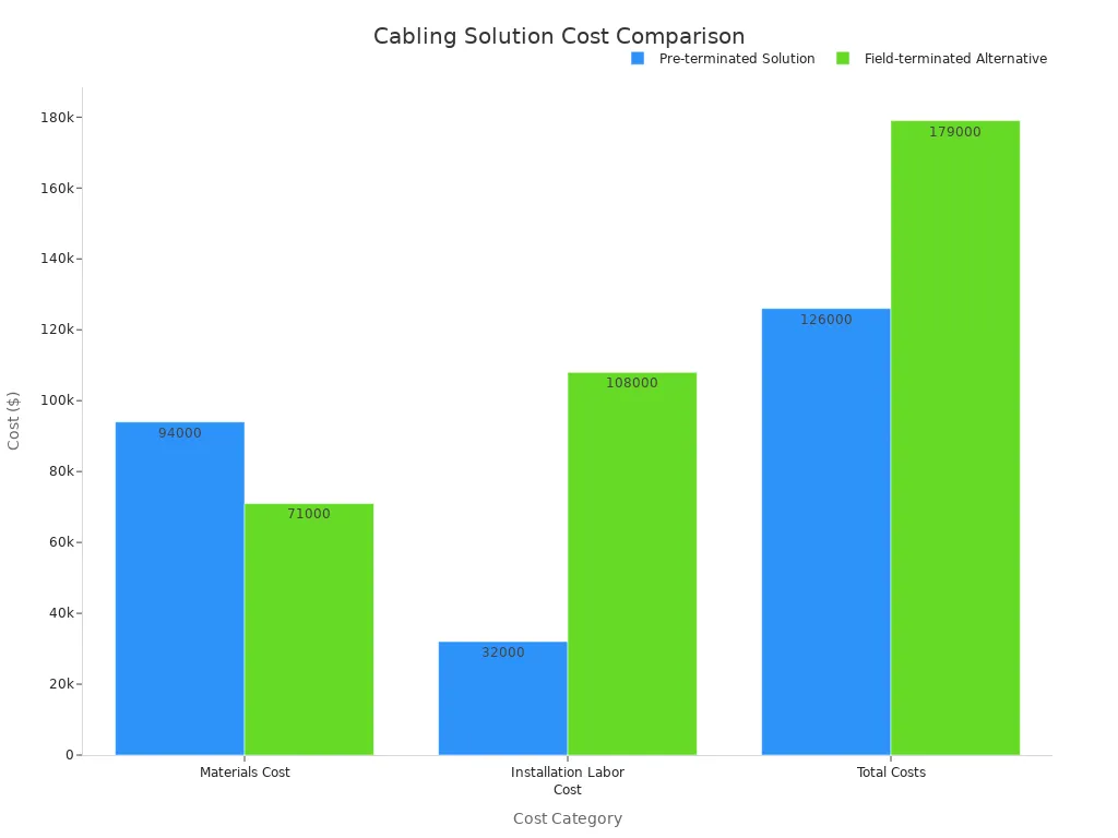
| Cost Category | Pre-terminated Solution | Field-terminated Alternative |
|---|---|---|
| Materials Cost | $94,000 | $71,000 |
| Installation Labor Cost | $32,000 (384 hours) | $108,000 (1,260 hours) |
| Total Costs | $126,000 | $179,000 |
| Savings (Pre-terminated) | $53,000 | N/A |
Operational Costs for Installation
Installation labor costs represent a significant operational expense. Skilled fiber technicians charge $75-125 per hour. Installing pre-terminated trunk cables takes 0.5-0.8 hours per cable. Field termination takes 4-6 hours per cable. For a 100-cable deployment, this translates to $26,000-$69,000 in installation cost savings for pre-terminated solutions.
Structured cabling reduces average troubleshooting time by 40-50%. Network downtime costs $50,000-$100,000 per hour. Faster restoration provides substantial value. Factory terminations achieve 99.7% first-time success rates. Field terminations achieve 94-96%. The 3-5% defect rate in field terminations leads to additional technician time and potential service disruptions. Upgrading a 50-rack facility from 100G to 400G/800G costs $200,000-$400,000 with appropriate fiber infrastructure (OM4/OM5 or OS2). Complete recabling costs $500,000-$800,000. This represents a $300,000-$400,000 differential. This differential outweighs initial savings from under-specified cabling.
Staff Expertise and Training
The complexity of the chosen cabling solution impacts staff expertise and training needs. Pre-terminated MTP/MPO systems require less specialized on-site skills. This reduces the need for extensive training or hiring highly specialized technicians. This also lowers associated costs.
Specific Use Case Scenarios
New Data Center Build-Outs
New data center build-outs present an ideal opportunity to implement advanced cabling solutions. MTP/MPO trunk cables are perfect for these large-scale installations. They offer excellent scalability and future-proofing. These cables contain more fibers within a single jacket, simplifying cable management. This design allows for significant future expansion within data centers. Engineers recommend MTP/MPO trunk cables for long-distance transmissions. They consolidate many fiber strands into one, reducing bulkiness. This effectively uses space in high-fiber count environments. Their pre-terminated nature with MTP/MPO connectors significantly simplifies installation. This leads to quicker deployment times and easier maintenance.
MTP/MPO trunk cables also support high-speed parallel optic applications. For example, 8-fiber MPOs facilitate 200 Gbps and 400 Gbps applications. These use four transmitting and four receiving fibers at 50 or 100 Gbps. 16-fiber MPOs are essential for 800 Gbps applications, utilizing eight transmitting and eight receiving fibers at 100 Gbps. MTP connectors are the preferred choice for 100G and 400G backbone connections. They offer superior optical performance and consistent manufacturing quality. This is critical for maintaining link budgets. Data centers with limited space and massive cabling requirements benefit greatly from MTP/MPO solutions. MTP housings can hold significantly more fibers, such as 864 fibers in a 1U housing, compared to 144 in a 1U housing with duplex connections. This high density leads to measurable infrastructure cost savings in hyperscale deployments. It reduces the fiber panel footprint by 67% compared to LC duplex designs, freeing up valuable rack units. MTP/MPO trunk cables are ideal for high-speed trunk links. They provide direct connections for 40G, 100G, or 400G links between data centers, distribution frames, and cabinets. They support high-speed parallel transmission, crucial for these high-bandwidth applications. Their design simplifies the overall cabling infrastructure and conserves space within the data center.
Upgrading Existing Infrastructure
Upgrading existing data center infrastructure often involves a mix of MTP/MPO trunk and breakout cables. Trunk cables can replace older, lower-density cabling. This immediately boosts backbone capacity. For instance, replacing multiple individual fiber runs with a single MTP/MPO trunk cable streamlines pathways. It also prepares the network for higher speeds. Breakout cables offer crucial flexibility during upgrades. They allow seamless integration of new high-speed switches with existing servers or network devices that use lower-speed ports. A 100G switch port can connect to four 25G servers using a breakout cable. This avoids a complete overhaul of server-side cabling. This approach maximizes the use of new high-speed equipment while preserving investments in existing hardware. It also simplifies the transition to higher bandwidths without extensive re-cabling.
High-Performance Computing Clusters
High-Performance Computing (HPC) clusters demand extremely low latency and high bandwidth. MTP/MPO trunk cables form the backbone of these environments. They provide the necessary high-speed, high-density connections between core switches and compute racks. This ensures rapid data transfer across the cluster. The pre-terminated nature of trunk cables also allows for quick deployment of new racks or expansion of existing ones. Breakout cables play a vital role in connecting individual compute nodes within the HPC cluster. They link high-speed switch ports to multiple server network interface cards (NICs). This optimizes port utilization on expensive HPC switches. For example, a 400G switch port can break out into multiple 100G or 50G connections for individual servers. This configuration ensures each node receives ample bandwidth. It also minimizes latency, which is critical for parallel processing tasks. The high density and performance of MTP/MPO solutions are indispensable for the demanding requirements of HPC clusters.
Best Practices for Implementation
Successful data center cabling relies on meticulous planning and execution. Adhering to best practices ensures network reliability, scalability, and ease of maintenance.
Proper Planning and Design
Effective planning forms the backbone of a robust cabling infrastructure.
Cable Routing and Management
Proper cable routing and management are crucial. They prevent signal interference and maintain optimal airflow. Technicians should use cable trays, conduits, and Velcro ties. This keeps cables organized and prevents damage. Good management also simplifies future upgrades and troubleshooting.
Polarity Management
Polarity management is essential for MTP/MPO systems. Network designers must select a consistent polarity method (Type A, B, or C) for the entire link. This ensures transmit signals connect to receive signals correctly. Inconsistent polarity leads to communication failures.
Documentation and Labeling
Comprehensive documentation and labeling are indispensable. They streamline troubleshooting and future modifications. Data centers should implement clear labeling standards. These standards include legible, commercial-grade labels and color-coding schemes. For instance, blue often signifies horizontal copper cables, while red indicates security or emergency circuits. Adhering to industry standards like TIA-606-C and ISO/IEC 14763-2 ensures consistency. These standards promote hierarchical labeling, consistent identification, and accurate record-keeping. Maintaining up-to-date cabling diagrams and network documentation is also vital for easy reference.
Testing and Certification
Thorough testing and certification validate the performance of the cabling infrastructure.
End-to-End Testing
End-to-end testing verifies the entire cable link. This includes all connectors and splices. It confirms the link meets performance specifications. This step identifies potential issues before deployment.
Power Meter and OTDR
Technicians use specific tools for fiber optic testing. A power meter measures optical loss. An Optical Time Domain Reflectometer (OTDR) locates faults and measures cable length. These tools provide critical data about cable health.
Standards Compliance
Cabling must comply with industry standards. Tier-1 certification covers loss and length measurements. Tier-2 certification adds OTDR testing. These tiers apply to both multimode and singlemode fiber optic cabling. The IEC 61300-3-35 standard guides the inspection and certification of fiber end faces. This ensures high-quality connections and prevents common network issues.
Maintenance and Troubleshooting
Regular maintenance and efficient troubleshooting keep the network running smoothly.
Cleaning Procedures
Fiber optic connectors require regular cleaning. Dust and contaminants cause signal loss and network errors. Technicians should use proper cleaning tools and techniques. This maintains optimal signal integrity.
Fault Isolation
Effective fault isolation quickly identifies and resolves network problems. Good documentation and labeling aid this process. Technicians can trace cables and pinpoint issues faster. This minimizes downtime.
Spare Parts Inventory
Maintaining a spare parts inventory is a best practice. This includes spare cables, connectors, and transceivers. Having these parts readily available reduces repair times. It ensures quick recovery from unexpected failures.
---


The optimal choice between MTP/MPO trunk and breakout cables depends on specific data center applications. MPO trunk cables are essential for building [high-density](https://www.newsunn.com/mpo-24-high-density-cabling-eu-data-center-compliance/), scalable backbone infrastructure. They support the core of the network efficiently. Breakout cables provide flexible, direct connectivity to individual devices. They connect servers and switches with ease. A well-informed decision ensures an efficient, scalable, and cost-effective data center network. This strategic choice significantly impacts long-term network performance and adaptability.

## FAQ


### What is the primary difference between MTP/MPO trunk and breakout cables?
MTP/MPO trunk cables connect high-density MTP/MPO ports directly. They maintain the same fiber count on both ends. Breakout cables convert a single MTP/MPO port into multiple lower-speed ports, typically LC or SC. They connect high-density ports to individual devices.

### When does a data center typically use MTP/MPO trunk cables?
Data centers use MTP/MPO trunk cables for high-density backbone infrastructure. They connect core switches, distribution switches, and inter-rack equipment. These cables are essential for high-speed SANs and future 400G/800G networks.

### What are the ideal applications for MTP/MPO breakout cables?
Breakout cables are ideal for server-to-switch connections and Top-of-Rack architectures. They integrate with patch panels and interface with legacy equipment. They allow a single high-speed port to connect multiple lower-speed devices.

### How do MTP/MPO cables contribute to future-proofing a network?
MTP/MPO cables support current and future high-speed Ethernet standards. Their high density and modular design allow easy upgrades to 400G, 800G, and beyond. They accommodate new devices and offer flexibility for reconfigurations.

### What benefits do pre-terminated MTP/MPO cables offer during installation?
Pre-terminated MTP/MPO cables significantly reduce installation time and labor. They ensure consistent performance and quality. They also minimize the need for specialized on-site tools and skills.

### Why is polarity management important for MTP/MPO systems?
Polarity management ensures correct signal transmission. It aligns transmit and receive signals properly. Inconsistent polarity leads to communication failures. Proper documentation and consistent methods prevent issues.

### Can breakout cables help reduce overall network costs?
Yes, breakout cables can reduce costs. They maximize switch port utilization, avoiding stranded ports. This allows a single expensive high-speed port to serve multiple lower-speed devices. This optimizes resource use and lowers hardware expenses.