
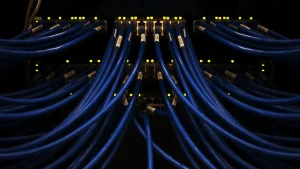


Mastering MPO/MTP to LC/SC/ST/FC breakout cable installation is critical for network professionals. This expertise directly ensures network resilience and operational efficiency. Deploying an MPO Breakout Harness Cable OM3/OM4/OS2 correctly provides significant strategic advantages. Professionals who understand these connections and MPO trunk deployments can navigate the rapidly evolving digital landscape effectively. This knowledge guarantees robust and high-performing network infrastructures.
Key Takeaways
- MPO/MTP breakout cables are important for modern networks. They help manage lots of data in small spaces.
- These cables support very fast internet speeds. They are good for 400G Ethernet and even faster connections.
- Using MPO/MTP cables saves time and money. They are easy to set up and make networks ready for the future.
- Bad installation of these cables causes big problems. It can make the network slow and cost more money to fix.
- Always check and clean cables before you install them. This stops dirt from causing signal problems.
- Understand how to connect the cables correctly. This is called polarity and it makes sure data goes the right way.
- Use the right tools for installation and testing. Tools like fiber scopes help check cable quality.
- Keep learning about new cable technologies. This helps your team stay good at network setup.
The Indispensable Role of MPO/MTP to LC/SC/ST/FC Breakout Cables in Modern Networks
Meeting High-Density Demands in Data Centers
Exponential Data Growth and Space Optimization
Data centers experience exponential data growth. This growth demands efficient space utilization. MPO/MTP cables offer a solution. They consolidate multiple fiber strands into a single connector. This design significantly reduces cable bulk. It optimizes valuable rack space within crowded data center environments. Network architects can deploy more connections in less physical area.
Scalable Interconnects for Distributed Architectures
Modern networks often feature distributed architectures. These architectures require scalable interconnects. MPO/MTP breakout cables provide this scalability. They allow for easy expansion and reconfiguration. Network professionals can quickly add or modify connections. This flexibility supports the dynamic needs of growing data centers. It ensures the infrastructure remains agile.
Enabling 400G and Beyond with MPO/MTP to LC/SC/ST/FC Solutions
Bandwidth Requirements and Parallel Optics
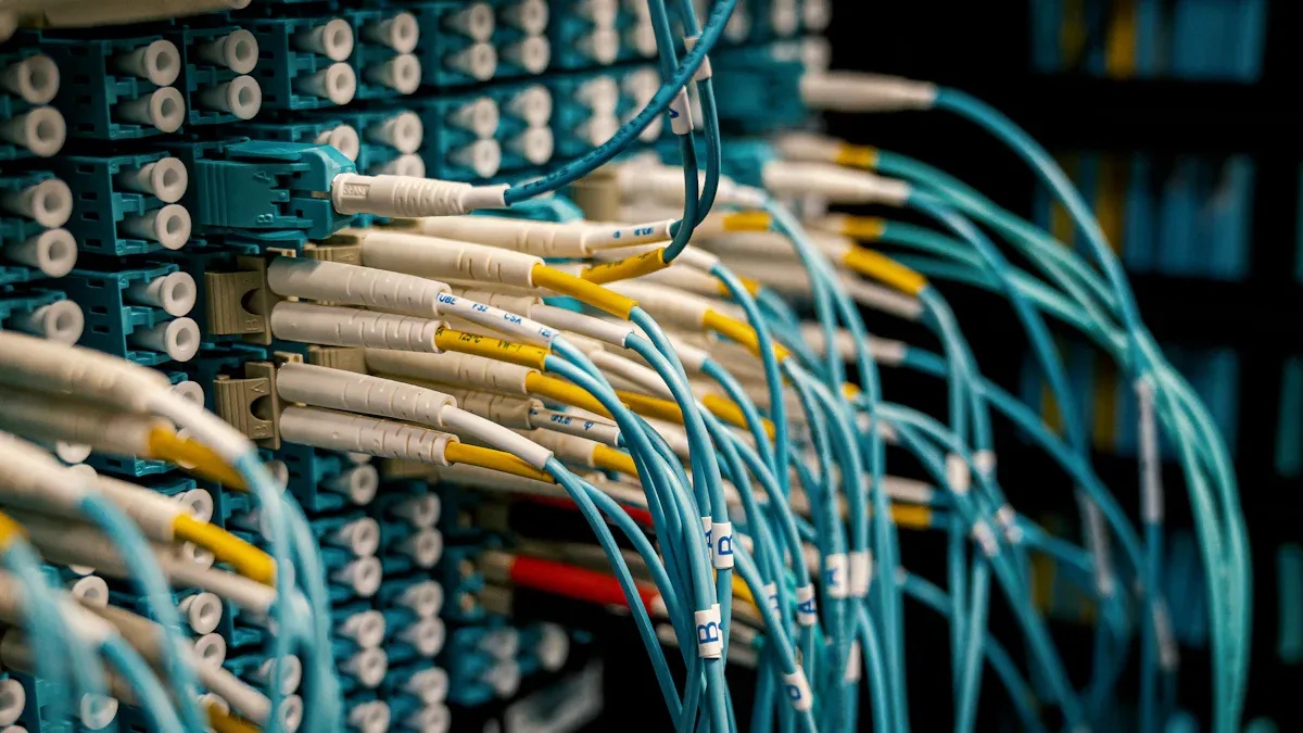
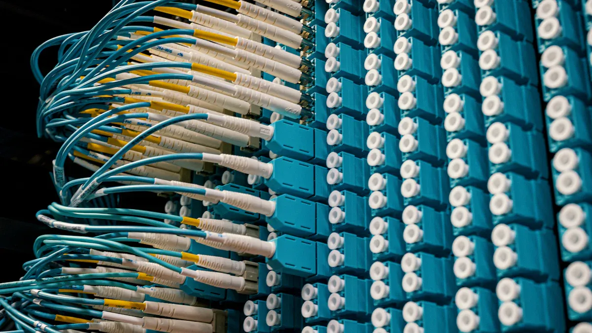
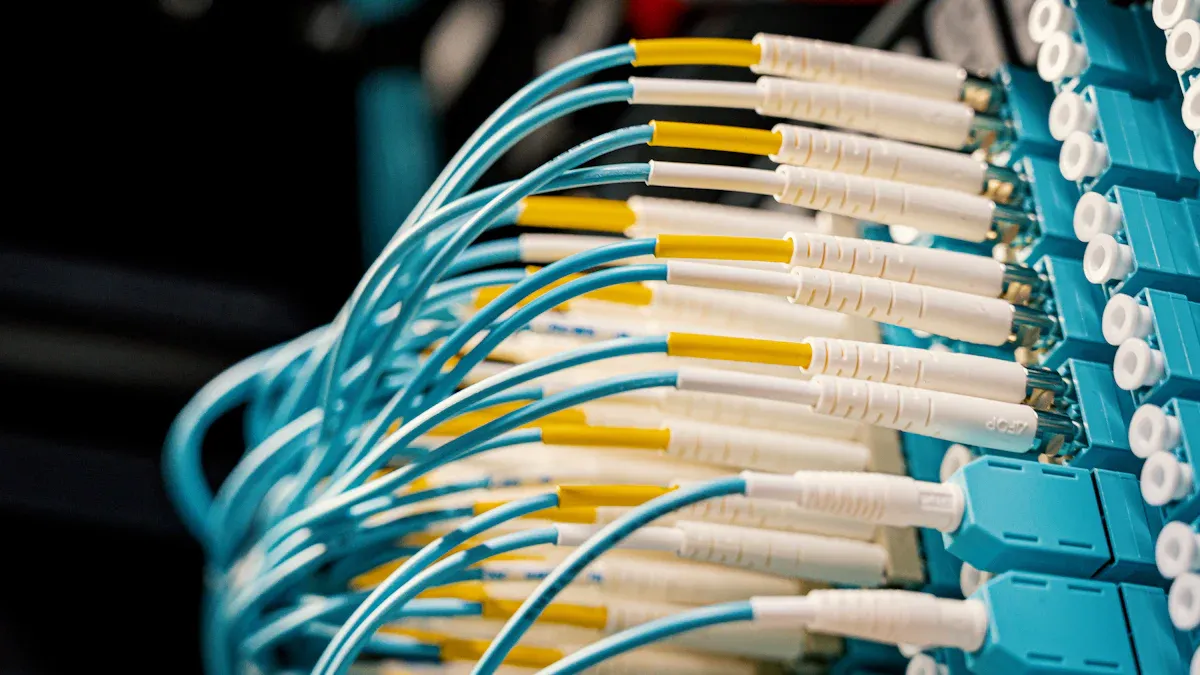
The demand for higher bandwidth continues to rise. Networks now require support for 400G Ethernet and beyond. MPO/MTP connectors are crucial for these high-speed links. They support parallel optics technology. This technology transmits data over multiple fibers simultaneously. MPO/MTP connectors, including the enhanced MTP version, can support 12, 24, or more fibers within a single connector. They are essential for 400G Ethernet deployments and building ultra-high-density network backbones. MTP/MPO connectors are the preferred choice for ultra-high-speed, high-density networks, especially for 400G/800G links in data centers. They connect switches to top-of-rack panels, often using 12-fiber MTP/MPO cables. LC connectors also play a vital role. They are suitable for 10G–400G links. Their 1.25mm ferrule design maximizes port density, making them a top choice in data center environments.
Low Latency Connectivity for Edge Computing
Edge computing relies on low latency connectivity. Data processing occurs closer to the source. This setup minimizes delays. MPO/MTP to LC/SC/ST/FC breakout cables contribute to achieving low latency. They provide direct, high-speed connections. This directness reduces signal travel time. It ensures rapid data transfer for critical edge applications.
Versatility Across Applications
Internal Connector Applications in Fiber Equipment
MPO/MTP to LC/SC/ST/FC breakout cables demonstrate significant versatility. They serve as internal connectors within various fiber equipment. Examples include splitters, 40G SFP, and 100G SFP+ transceivers. These cables facilitate the internal routing of optical signals. They ensure efficient operation of the equipment.
Connecting Trunk Backbone Assemblies to Rack Systems
These cables also bridge trunk backbone assemblies to rack systems. Trunk cables provide the main fiber optic pathways. Breakout cables then distribute these fibers to individual ports on switches or servers. This connection method simplifies cabling. It provides a clean and organized network infrastructure.
Unlocking Efficiency and Scalability with MPO/MTP to LC/SC/ST/FC Breakout Cables
Rapid Deployment and Reduced Installation Time
Streamlined Setup for High-Density Environments
Network professionals constantly seek methods to accelerate infrastructure deployment. MPO/MTP breakout cables significantly streamline setup processes, especially in high-density data center environments. Their pre-terminated, modular design eliminates the need for time-consuming field terminations. This approach drastically reduces the number of individual connections technicians must make. MPO/MTP-LC breakout cables offer faster deployment due to their modular design. This shortens network build time and simplifies the cabling process by reducing connection points. This efficiency allows for quicker activation of new racks and equipment.
Modular Design for Quick Upgrades
The modular nature of MPO/MTP cabling systems facilitates rapid upgrades and reconfigurations. Technicians can quickly connect or disconnect multi-fiber cables, minimizing disruption to active services. This design supports a "plug-and-play" philosophy for fiber optic infrastructure. MPO/MTP breakout cables significantly reduce fiber installation time by 75-80% compared to traditional field-terminated methods. This efficiency can transform projects that would typically take a week into day-long deployments. Such speed is invaluable in dynamic data center operations where time equals money.
Future-Proofing Your Infrastructure
Adaptability for Evolving Network Standards
Investing in network infrastructure requires foresight. MPO/MTP cabling systems offer exceptional adaptability for evolving network standards. They support current high-speed requirements and provide a clear upgrade path for future technologies. Proper installation and maintenance allow fiber optic cabling systems to last 15 years or more, spanning multiple hardware generations. MPO/MTP architectures simplify high-density, modular growth. This allows for seamless upgrades to higher speeds and contributes to a future-ready lifecycle strategy.
Easy Expansion and Hardware Optimization
MPO/MTP solutions simplify network expansion. Organizations can easily add capacity without extensive re-cabling. This modularity also optimizes hardware utilization. They can connect multiple devices to a single MPO/MTP trunk, maximizing port density on switches and patch panels. This approach ensures the infrastructure remains agile and responsive to increasing bandwidth demands.
A data center planned for 40G but installed OM4 cabling and 12-fiber MTP—now seamlessly upgraded to 400G using breakout modules.
Cost-Effectiveness and Return on Investment
Lower Labor Costs and Operational Expenses
The initial investment in structured cabling, including MPO/MTP to LC/SC/ST/FC breakout cables, yields substantial long-term savings. Rapid deployment translates directly into lower labor costs. Fewer hours are spent on installation and troubleshooting. This efficiency reduces overall operational expenses. The simplified management of these high-density cables also minimizes ongoing maintenance efforts.
Maximizing Hardware Utilization
MPO/MTP cabling helps maximize the utilization of expensive network hardware. By consolidating multiple connections into a single cable, it frees up valuable port space on switches and servers. This optimization delays the need for additional hardware purchases. While structured cabling has an initial upfront cost, the return on investment manifests in various forms. These include reduced downtime, lower energy consumption, faster maintenance, easier compliance audits, and the flexibility to adopt new technologies without extensive rewiring. Over a decade, the operational savings and avoided disruptions typically surpass the initial investment significantly.
Consider a practical example: A B2B SaaS company, operating with extreme density requirements in a single colocation rack, deployed MTP cabling for 400G links. While MTP added $3,400 to their infrastructure budget, it allowed them to avoid leasing a second rack, which would have cost $4,800 per month. This strategic investment resulted in an ROI being achieved in just 26 days. This case demonstrates the tangible financial benefits of adopting MPO/MTP solutions.
Avoiding Pitfalls: The Consequences of Poor MPO/MTP to LC/SC/ST/FC Installation
Improper installation of fiber optic cabling, especially MPO/MTP to LC/SC/ST/FC breakout cables, creates significant risks for network infrastructure. These errors lead to a cascade of negative outcomes, impacting performance, operational efficiency, and financial stability. Network professionals must understand these potential pitfalls to prevent them.
Performance Degradation and Network Instability
Signal Loss and Attenuation Issues
Poor installation practices directly cause signal loss and attenuation. Incorrect fiber handling, improper connector cleaning, or inadequate strain relief introduce micro-bends and macro-bends in the fiber. These physical stresses impede light transmission. Contaminated connector end-faces also block optical signals. Such issues reduce the overall signal strength, making data transmission unreliable.
Unreliable Network Performance
Signal degradation translates into unreliable network performance. Data packets experience errors, requiring retransmission. This increases latency and reduces effective bandwidth. Users experience slow network speeds, dropped connections, and application failures. A network built on faulty fiber connections cannot consistently deliver the expected performance, undermining its core purpose.
Troubleshooting Complexities and Downtime
Difficult Fault Isolation
Poorly installed MPO/MTP to LC/SC/ST/FC connections make fault isolation extremely difficult. Technicians face challenges identifying the exact point of failure within a dense cabling environment. Unlabeled or improperly routed cables further complicate the diagnostic process. This extended troubleshooting time delays problem resolution.
Increased Mean Time to Repair
The difficulty in isolating faults directly increases the Mean Time to Repair (MTTR). Network outages persist longer as teams struggle to pinpoint and rectify issues. Prolonged downtime impacts business operations and user productivity. Efficient network recovery depends heavily on a well-installed and documented infrastructure.
Financial and Reputational Impact
Unforeseen Operational Costs
Faulty fiber optic installations lead to significant unforeseen operational costs. Poorly installed fiber necessitates more frequent repairs, increasing maintenance expenses. Organizations face higher long-term capital investment due to premature component replacement. Supply chain issues can force expensive expedited shipping for crucial components during emergencies, raising overall infrastructure costs. Dense and disorganized fiber cabling obstructs airflow, leading to higher cooling demands and energy inefficiency, thereby increasing operational expenses.
Client Dissatisfaction and Service Interruptions
Persistent performance problems result in service interruptions. Damaged fiber connections lead to a loss of internet, telecommunications, or data transfer services. This is particularly detrimental for businesses reliant on these services. Such issues cause customer dissatisfaction, leading to SLA violations and diminished customer trust. Financial penalties often accompany these service failures. Service interruptions and downtime contribute to lost productivity, missed opportunities, and significant financial losses for businesses.
Best Practices for Installing MPO/MTP to LC/SC/ST/FC Breakout Cables
Proper installation of MPO/MTP to LC/SC/ST/FC breakout cables ensures network reliability and performance. Adhering to best practices minimizes errors and prevents costly downtime. Network professionals follow established procedures for optimal results.
Pre-Installation Inspection and Planning
Thorough preparation forms the foundation of a successful fiber optic deployment. This stage involves meticulous checks and strategic decisions.
Ensuring Pristine Cable and Connector Condition
Inspect all cables and connectors before installation. This step prevents issues arising from manufacturing defects or transit damage. Technicians visually examine connectors for dust, dirt, or other contaminants, especially for MTP® and MPO cable systems. They gently clean end faces with appropriate tools like lint-free wipes, isopropyl alcohol, and compressed air. This ensures no residue remains. For more thorough cleaning, automated cleaners specifically designed for MTP® connectors provide consistent results. Periodic inspections under a fiber inspection microscope detect tiny particles that could hinder performance. Always store connectors with protective caps when not in use. This prevents dust accumulation and reduces contamination, thereby increasing their lifespan.
Industry standards guide MTP/MPO fiber testing. The IEC (International Electrotechnical Commission) sets international standards for fiber geometry, attenuation, macrobending loss, and dispersion. TIA/EIA (Telecommunications Industry Association and Electronics Industry Alliance) develops national standards for fiber optic test networks and equipment. These cover aspects like installation certification requirements for fiber length, polarity, and link loss.
Pre-installation inspection of MTP/MPO connectors includes checking whether the fibers’ polarity and sequence within the connectors properly align with network equipment and patch panels. This step is essential for maintaining the integrity of MPO fiber systems and preserving signal integrity. An MTP/MPO fiber continuity test confirms the link’s integrity. This ensures no fiber breaks and that the optical signal smoothly reaches the end of the link. This test typically uses a visual fault locator (VFL). A VFL emits visible light to help identify and locate fiber link faults such as bends, breaks, and connection issues. Eye protection is advised when using a VFL.
The IEC 61300-3-35 standard provides specific cleanliness grading criteria for assessing pass or fail certification during fiber end face inspection. This standard defines cleanliness based on the number and size of scratches and defects in various regions of the end face. This eliminates human subjectivity and potential disputes.
Cable Path Optimization and Connector Type Selection
Plan the cable path carefully. This avoids sharp bends, kinks, and excessive tension. Proper routing prevents physical damage to the fibers. Select the correct connector types (LC, SC, ST, FC) based on the equipment interfaces. This ensures compatibility and optimal performance. Consider future expansion needs when designing the cable layout.
Proper Handling and Cleaning Techniques
Contamination remains a leading cause of fiber optic network failures. Proper handling and cleaning are paramount.
Preventing Contamination of Connectors
Proper cleaning is crucial for preventing network failures. Dirty connectors are a major cause of issues. Technicians mitigate contamination risk by using fiber optic cleaners, cleaning pens, and wipes. These tools remove contaminants like dust, dirt, oils, film residue, and solvent coating. Airborne dirt particles, similar in size to single-mode fiber cores and often silica-based, can scratch PC connectors if not removed. Mating adapters in patch panels can become contaminated if left open or through repeated use. Always use dust caps on connectors, bulkhead splices, patch panels, or any connection points to prevent contamination.
Every fiber end face, including MPO connectors, should be inspected and cleaned if necessary before connection. Due to the larger surface area of MPO connectors, cleaning and inspecting are even more critical, as contaminants can spread between fibers within the array. For MPO connectors with a higher fiber count (e.g., 16- or 24-fiber), height differentials between fibers make proper and equal cleaning more challenging, increasing the importance of inspection. It is crucial to inspect, and if needed, clean and then inspect again to ensure cleanliness.
Utilizing Approved Cleaning Tools
Use only approved cleaning tools for fiber optic connectors. These tools ensure effective contaminant removal without damaging the delicate end faces. Recommended tools include:
- One-Click Cleaners: Available for SC, ST, FC, LC, MU, and MPO connectors.
- FCC2 Fiber Cleaning Fluid: A specialized fluid for fiber cleaning.
- FCC3 Debris Destroyer™: Designed to remove debris.
- FiberWipes: For effective cleaning.
- Cletop SB: A fiber cleaning cassette.
- 1.25mm One-Click Cleaner Pen: Specifically for SC, ST connectors.
- 2.50mm One-Click Cleaner Pen: Specifically for LC, MU connectors.
- One-Click Cleaner for MPO Connectors: A dedicated tool for MPO connectors.
Mastering Termination and Polarity Management
Correct termination and polarity management are critical for proper signal flow in multi-fiber systems.
Understanding A/B/C Polarity Methods
MTP/MPO polarity type verification is crucial. It ensures the transmitter (TX) correctly corresponds to the receiver (RX). Incorrect polarity leads to signals transmitting in the wrong direction, impacting network performance. Different polarity schemes (A, B, and C types) exist. Potential flips occur during connection and installation. Testing confirms the optical cable’s polarity type and ensures signal transmission along the correct channel. Failure to identify polarity issues results in unnecessary equipment replacement, increased costs, and network delays.
Industry standards identify three different polarity methods for MPO cables:
| Polarity Type | Description of Fiber Swap | Cable Type Characteristic |
|---|---|---|
| Type A | Achieves swap using two different patch cable configurations (one pair-flipped, one straight-through) at each end. Cassettes and trunk cable are straight-through. | Considered ‘straight through’ (Pin 1 to Pin 1). Can be interchanged with Type B by reversing housing. |
| Type B | Achieves swap using special ‘Key-up/Key-up’ adapters on straight-through cassettes and a Type B rollover trunk cable. | Considered ‘Reversed’, ‘Crossed’, or ‘Rollover’ (Pin 1 to Pin 12). Can be interchanged with Type A by reversing housing. |
| Type C | Achieves swap directly within the trunk cable, which is a Type C ‘Pair-Flipped’ cable. | Considered ‘Flipped’, ‘Pair-Flipped’, or ‘Swapped’ (Pin 1 to Pin 2 / Pin 2 to Pin 1). Cannot be changed. |
- Method A: Uses Type A straight-through MPO trunk cables with a key-up connector on one end and a key-down connector on the other. Fiber in Position 1 arrives at Position 1. For duplex applications, a transceiver-receiver flip is required in a patch cord at one end.
- Method B: Uses key-up connectors on both ends to achieve the transceiver-receiver flip. Fiber in Position 1 arrives at Position 12, Position 2 at Position 11, and so on. For duplex applications, Method B uses straight A-B patch cords on both ends.
- Method C: Uses a key-up connector on one end and a key-down connector on the other, similar to Method A. However, the flip occurs within the cable itself, where each pair of fibers is flipped (e.g., Position 1 arrives at Position 2, and Position 2 at Position 1). This method is suitable for MPO trunk cables in duplex applications but not for parallel fiber applications.
Correct Connector Keying and Alignment
Ensure correct connector keying and alignment during installation. MPO connectors have a key that dictates their orientation. Proper keying ensures fibers align correctly within the mating adapter. Misalignment leads to signal loss and poor performance. Always verify the keying orientation before mating connectors. This prevents damage to the ferrule and ensures proper optical contact.
Advanced Management and Maintenance of MPO/MTP to LC/SC/ST/FC Deployments
Rigorous Testing and Certification Protocols
Insertion Loss Testing for Performance Validation
Network professionals perform insertion loss testing to validate fiber optic cable performance. This test measures the signal power lost when light passes through a connection or a length of fiber. Low insertion loss ensures optimal signal strength and reliable data transmission. Technicians use Optical Loss Test Sets (OLTS) for accurate measurements. These tests confirm the installed cabling meets industry standards and specific project requirements.
End-Face Inspection for Quality Assurance
End-face inspection is a critical step for quality assurance. Technicians visually examine connector end-faces for defects, scratches, or contamination. Even microscopic particles can cause significant signal degradation. Fiber inspection scopes provide detailed views of the end-face. This allows for thorough cleaning and ensures pristine connections before mating. Regular inspection prevents performance issues and extends the lifespan of the fiber infrastructure.
Comprehensive Documentation and Labeling Standards
Clear Cable Identification and Network Mapping
Documentation of the cable plant and network is vital for future reference and problem resolution. Clear cable identification and network mapping are essential practices. Professionals document cable location, fiber paths, interconnections, and test results. They record detailed specifications for each cable and fiber, including manufacturer, type, fiber count, construction, and estimated length. This comprehensive record includes hardware, panels, and end equipment, noting any dark or unterminated fibers.
Facilitating Future Maintenance
Effective documentation significantly facilitates future maintenance. Technicians label all components with permanent, color-coded labels, using a simple and consistent scheme. This practice eases tracing links and finding faults during troubleshooting. It also speeds up cable installation and testing. Organizations maintain multiple backup copies of all documentation in different locations, both digital and physical. They keep documentation updated by assigning responsibility to an on-site person. This prevents unauthorized changes. Documentation is crucial for future expansion, rerouting for repairs, or moving network equipment. It provides reference in case of future cabling problems requiring emergency restoration.
Troubleshooting Common Issues in MPO/MTP to LC/SC/ST/FC Connections
Identifying Connection Problems
Identifying connection problems quickly minimizes network downtime. Technicians always clean both connector ends with lint-free wipes or a proper fiber cleaner before plugging them in. Even small dust particles disrupt signals or cause reflection issues. They check polarity and orientation, especially for duplex LC or multi-fiber connectors, to prevent data misdirection or loss. Technicians insert connectors with gentle, straight pressure. For threaded types, they tighten just enough without over-torquing.
Resolving Performance Bottlenecks
Resolving performance bottlenecks requires systematic troubleshooting. Technicians keep cables organized and labeled, avoiding sharp bends or pulling. This protects connections long-term. After installation, they use a power meter or similar tool to test each connection’s signal strength. This confirms proper operation. Regular inspection of connectors for dirt, scratches, or damage is important. Technicians use a fiber scope for closer examination if available. Even minor flaws impact signal flow. If a connector is unplugged, they clean it again before re-connecting. This removes accumulated dust or oils. They always cover unused connectors and ports with dust caps. This protects them from airborne contaminants.
Equipping Your Team: Training and Tools for MPO/MTP to LC/SC/ST/FC Mastery in 2025
Network professionals require the right training and tools to achieve mastery in fiber optic installations. Equipping teams with essential resources ensures efficient, reliable, and future-proof network deployments. This proactive approach safeguards network integrity and operational excellence.
Essential Tools for Installation and Testing
Proper installation and testing of fiber optic cables demand a specific set of tools. Technicians rely on these instruments for precision and accuracy.
Fiber Inspection Scopes and Optical Power Meters
Fiber inspection scopes are indispensable. They allow technicians to visually inspect connector end-faces for contamination or damage. Optical power meters measure the signal strength. This confirms proper light transmission and identifies potential signal loss issues. These tools are critical for validating performance and ensuring quality.
MPO/MTP Adaptors and Cassettes
MPO/MTP adaptors and cassettes facilitate organized and efficient connectivity. They provide a structured interface for multi-fiber cables. Essential tools for installation and testing include:
- MPO-12 breakout cables
- Fiber optic connectors (LC/SC/FC/ST)
- Fiber optic cleaver and stripper
- Cleaning tools (isopropyl alcohol, lint-free wipes)
- Fiber optic tester
- Safety gear (gloves, safety glasses)
- Fiber strippers
- Cleavers
- Crimping pliers
- Cleaning kits
- Cable management accessories
- MPO-specific test sets
- Microscopes
- Light sources
- Power meters
- Polarity testers
Continuous Learning and Certification
The fiber optic landscape evolves rapidly. Continuous learning and certification keep teams at the forefront of technology.
Staying Current with Industry Best Practices
Industry best practices change as new technologies emerge. Teams must stay updated on the latest installation techniques, testing methodologies, and safety standards. Regular training ensures technicians apply the most effective and efficient procedures. This commitment to ongoing education enhances overall network reliability.
Vendor-Specific Training for MPO/MTP to LC/SC/ST/FC Solutions
Many manufacturers offer specialized training for their products. Vendor-specific courses provide in-depth knowledge of particular MPO/MTP to LC/SC/ST/FC solutions. This training ensures technicians maximize the performance and longevity of specific hardware. It also helps them troubleshoot vendor-specific issues effectively.
Building an Expert Team
Developing an expert team requires strategic investment in human capital. Skilled professionals are the backbone of a robust network infrastructure.
Skill Development Programs
Organizations implement structured skill development programs. These programs cover fundamental fiber optic principles and advanced MPO/MTP deployment strategies. Practical, hands-on training builds confidence and competence among technicians. A well-trained team executes complex installations with precision.
Knowledge Sharing Initiatives
Fostering a culture of knowledge sharing strengthens the entire team. Experienced technicians mentor newer colleagues. Regular workshops and internal forums allow for the exchange of insights and best practices. This collaborative environment ensures collective expertise grows, benefiting all network operations.
Mastering MPO/MTP to LC/SC/ST/FC breakout cable installation is critical for future-proof networks. This expertise ensures superior performance, enhanced scalability, and significant cost-efficiency. Network professionals gain a strategic advantage. Organizations achieve robust, adaptable infrastructures. This skill set drives operational excellence and prepares networks for future demands.
FAQ
What is an MPO/MTP to LC/SC/ST/FC breakout cable?
An MPO/MTP to LC/SC/ST/FC breakout cable connects a multi-fiber MPO/MTP connector to several individual simplex or duplex connectors like LC, SC, ST, or FC. It allows for the distribution of high-density fiber links to standard equipment ports.
Why are these cables essential for modern data centers?
These cables are crucial for managing high-density environments. They optimize space, simplify cabling, and support the exponential data growth in data centers. They also enable scalable interconnects for distributed network architectures.
What network speeds do MPO/MTP breakout cables support?
MPO/MTP breakout cables support very high network speeds. They are vital for 40G, 100G, 400G Ethernet, and beyond. They utilize parallel optics technology to transmit data over multiple fibers simultaneously.
What are the main advantages of using MPO/MTP breakout cables?
MPO/MTP breakout cables offer rapid deployment and reduced installation time. They provide future-proofing for infrastructure and deliver cost-effectiveness. Their modular design allows for quick upgrades and easy expansion.
What risks arise from incorrect MPO/MTP cable installation?
Incorrect installation leads to significant performance degradation and network instability. It causes signal loss, increases troubleshooting complexities, and extends downtime. This results in unforeseen operational costs and client dissatisfaction.
How does one ensure correct polarity in MPO/MTP installations?
Ensuring correct polarity involves understanding A/B/C polarity methods. Technicians verify that the transmitter correctly aligns with the receiver. Proper testing confirms the optical cable’s polarity type and ensures signal transmission along the correct channel.
What key tools are necessary for MPO/MTP cable installation?
Essential tools include fiber inspection scopes and optical power meters for testing. Technicians also use MPO/MTP adaptors and cassettes for connectivity. Cleaning kits, fiber strippers, and cleavers are also vital for proper installation.