


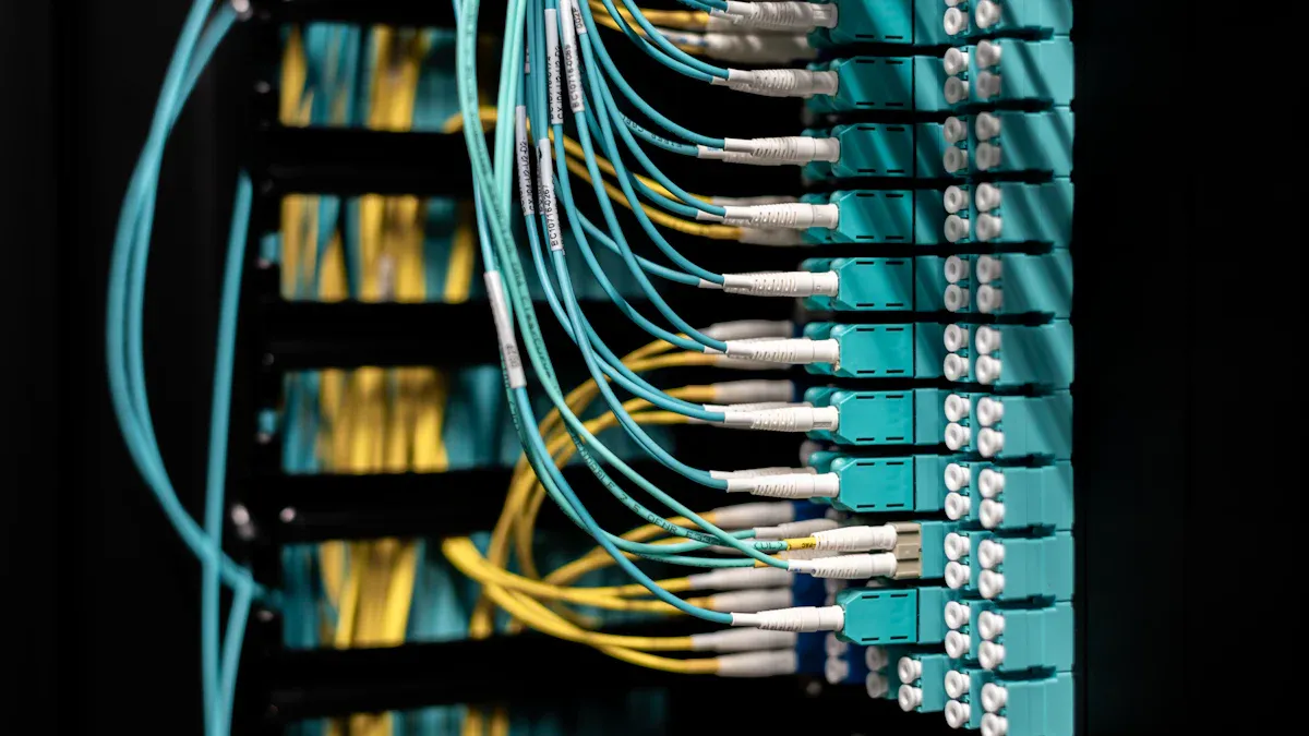
Network engineers recognize that proper MPO Adapter compatibility plays a vital role in maximizing uptime and throughput. Careful selection reduces signal loss and installation errors, which leads to smoother data transmission and fewer disruptions. High-quality components and correct polarity management keep fiber optic networks reliable, scalable, and easy to maintain.
Key Takeaways
- Choose the right MPO adapter type, fiber count, and gender to match your equipment and cables for smooth, reliable connections.
- Always verify and maintain correct polarity and key orientation to prevent signal loss and ensure proper data transmission.
- Regularly inspect and clean MPO adapters to avoid contamination and use low-loss, certified adapters to support high-speed, future-proof networks.
MPO Adapter Connector Type
Matching MPO Adapter to Equipment Ports
Selecting the correct MPO Adapter connector type ensures seamless integration with network equipment. Network engineers must consider several factors when matching adapters to ports:
- MPO connector types, such as Type A, B, and C, differ in polarity and wiring arrangement. These differences affect how adapters function in cabling systems and influence overall network design.
- MPO connectors come in male and female versions. Male connectors feature alignment pins, while female connectors have corresponding holes. This gender distinction determines how connectors mate with patch panels and equipment.
- Connector configurations vary by fiber count, including MPO-8, MPO-12, and MPO-24. Matching the fiber count of the adapter to the equipment port prevents connectivity issues and signal loss.
- MTP connectors, an advanced version of MPO, offer precision alignment pins that improve connection quality and reduce insertion loss.
Tip: Always inspect connectors for dust or debris before installation. Contamination, improper mating, and polarity issues frequently cause connectivity problems and signal loss.
Understanding MPO vs. MTP Adapter Differences
MPO and MTP adapters share similarities, but MTP connectors introduce enhancements that boost network performance and reliability. The table below highlights key differences:
| Feature | MPO Connector Characteristics | MTP Connector Enhancements and Impact |
|---|---|---|
| Pin Clamp | Plastic, prone to breaking | Metal, more durable and reliable |
| Ferrule | Fixed, less flexible | Floating, maintains contact under strain |
| Guide Pins | Flat-ended, more wear and debris | Elliptical, reduces wear and debris |
| Housing | Fixed | Removable, allows re-polishing and reworking |
| Insertion Loss | Higher (up to 0.75 dB) | Lower (up to 0.6 dB), better for high-speed |
| Compatibility | Standard MPO infrastructure | Interconnects with MPO, but not vice versa |
| Performance | Adequate for multi-fiber connections | Superior for high-density, high-speed networks |
MTP connectors provide lower insertion loss and greater durability, making them ideal for high-speed and long-distance applications. While MTP adapters can connect with MPO infrastructure, using MPO connectors in MTP-based systems may compromise compatibility and performance.
MPO Adapter Fiber Count
Single-Row vs. Multi-Row MPO Adapter Configurations
MPO adapters support a range of fiber counts, making them suitable for diverse network environments. Single-row MPO adapters typically house 12 or 16 fibers in a straight line. Multi-row configurations stack multiple rows, allowing for 24, 32, or even more fibers within the same connector footprint. This design enables higher density connections without increasing the physical size of the adapter.
- Standard MPO fiber counts include 8, 12, and 24 fibers.
- Specialty applications may require 32, 48, 60, or 72 fibers.
- Super high-density arrays can reach up to 144 fibers.
- Single-row adapters usually feature 12 or 16 fibers per row.
- Multi-row adapters combine these rows for greater capacity.
Multi-row MPO adapters prove essential in data centers and high-density LAN environments. They allow network engineers to maximize bandwidth while minimizing space requirements.
Aligning MPO Adapter with Cable Fiber Count
Selecting the correct fiber count for an MPO Adapter ensures compatibility with both current and future network needs. Most common configurations are MPO-12 and MPO-24, which align with standard cable assemblies and patch panels. Higher fiber counts, such as 48 or 72, support scalable network growth and simplify upgrades to higher data rates like 100G or 400G.
| Fiber Count | Typical Use Case | Scalability Impact |
|---|---|---|
| 12 | 40G/100G links, legacy | Standard density, easy upgrades |
| 24 | 100G/400G, new installs | High density, supports future expansion |
| 48+ | Data centers, backbone | Super high density, optimal for scaling |
Note: Choosing a higher fiber count reduces cable clutter and simplifies management, which becomes critical in high-density environments.
Proper alignment between adapter and cable fiber count ensures seamless installation, optimal performance, and long-term scalability.
MPO Adapter Polarity
Type A, B, and C MPO Adapter Polarity
Correct polarity in fiber optic networks ensures that transmit and receive signals align properly. MPO Adapter polarity follows three main methods: Type A, Type B, and Type C. Each method uses a different approach to maintain signal direction and fiber mapping.
| Polarity Method | Description | Fiber Positioning | Patch Cord Requirements | Application Notes |
|---|---|---|---|---|
| Method A | Maintains fiber positions at both ends with a 180° twist in the patch cord | Fiber 1 at position 1 on both ends | Requires two types of duplex patch cords (straight and cross) | Simplest to install and maintain; consistent connector orientation |
| Method B | Polarity flipped at one connector end; fiber 1 at position 12 and fiber 12 at position 1 | Fiber positions reversed at one end | Uses straight duplex patch cords at both ends | Requires precise installation knowledge; connector orientation appears the same at both ends |
| Method C | Adjacent fiber pairs flipped throughout the connector | Fiber 1 at position 2, fiber 2 at position 1, repeated | Uses straight duplex patch cords at both ends | Most complex; not suitable for 100GbE due to unusable fiber positions |
Type A offers the simplest installation and maintenance. Type B requires careful attention to connector orientation. Type C introduces complexity and does not suit high-speed applications like 100GbE.
Maintaining Signal Integrity with MPO Adapter Polarity
Maintaining correct polarity prevents signal transmission failures. When polarity errors occur, transmit signals do not reach the intended receive ports. This misalignment can cause heavy signal loss or complete network failure. Proper polarity ensures the transmit end of one device connects to the receive end of another, which is critical for reliable network performance.
- Polarity errors block signals from reaching receivers, especially in parallel transmission systems.
- Polarity test equipment verifies correct signal paths during installation.
- Standardized cabling schemes and consistent connectors help prevent errors.
- Professional polarity management software detects and corrects issues, reducing network failures.
Tip: Always verify polarity before finalizing MPO Adapter installations. This step protects network reliability and ensures optimal signal integrity.
MPO Adapter Key Orientation
Key-Up/Key-Down vs. Key-Up/Key-Up MPO Adapter Alignment
Key orientation in MPO adapters plays a crucial role in maintaining proper fiber alignment and network performance. The key, a physical feature on the connector, ensures correct insertion and fiber referencing. Industry standards, such as TIA 568.3-D, define two main alignment methods: Key-Up/Key-Down and Key-Up/Key-Up. In the Key-Up/Key-Down configuration, the key on one connector faces up while the mating connector’s key faces down. This method, known as Type A, maintains straight-through fiber mapping, where fiber 1 connects to fiber 1. In contrast, the Key-Up/Key-Up alignment, or Type B, positions both keys facing up. This reverses the fiber positions, so fiber 1 connects to fiber 12. These alignment methods correspond with different polarity schemes and wiring patterns, making careful selection essential for network compatibility.
Note: The key orientation also determines the starting point for fiber numbering, which is always from the left side of the key. This consistency is vital for inspection, splicing, and troubleshooting.
Preventing Mismatched MPO Adapter Connections
Proper key orientation prevents costly connection errors and signal loss. The physical keying mechanism blocks incorrect mating, which could otherwise cause crosstalk or data transmission failures. For example, using a Type A MPO Adapter ensures that fiber color codes and polarity remain intact, while a Type B adapter swaps fiber positions to match specific transceiver requirements. Technicians should standardize key orientation across the network and verify alignment during installation. Some adapters offer a removable key insert, allowing for easy polarity adjustments without replacing cables. This flexibility helps maintain network integrity and reduces downtime.
| Adapter Type | Key Orientation | Fiber Alignment | Effect on Polarity |
|---|---|---|---|
| Type A | Key-up to Key-down | Straight-through (1 to 1) | Maintains polarity |
| Type B | Key-up to Key-up | Reversed (1 to 12, 2 to 11, etc) | Swaps fibers for certain systems |
Tip: Always match the MPO Adapter key orientation to the system’s polarity scheme to avoid misalignment and ensure reliable signal transmission.
MPO Adapter Gender Compatibility
Male vs. Female MPO Adapter Connectors
MPO Adapter connectors come in two distinct types: male and female. Male MPO connectors include two protruding guide pins. These pins fit into corresponding holes in female connectors. This pin-and-hole mechanism ensures precise fiber alignment and stable signal transmission. In any MPO-to-MPO cable connection, one end must be male and the other female. Identical gender connectors cannot connect, which prevents improper mating and potential damage. When connecting MPO cables to optical modules, the cable must use a female connector. Optical modules typically have internal guide pins, so using a male connector could cause physical damage or misalignment. Matching the polarity type between male and female connectors also maintains signal integrity and prevents communication failures.
| Feature | Male MPO Connector | Female MPO Connector |
|---|---|---|
| Physical Design | Has two protruding guide pins for alignment | Has guide holes to receive male pins |
| Role in Connection | Aligns fibers precisely when mated | Receives male pins to ensure proper fit |
| Compatibility in MPO-to-MPO | Must be paired with female connector for proper insertion and firm connection | Must be paired with male connector for proper insertion and firm connection |
| Compatibility with Optical Modules | Usually not used directly; modules have internal pins (male) | Must be used to connect with optical modules (which have male pins) to avoid damage |
| Application Scenario | Used at one end of patch cords or MPO cassettes | Used to connect devices like optical modules |
| Importance of Polarity | Must match polarity type with female connector to maintain signal integrity | Must match polarity type with male connector to maintain signal integrity |
Avoiding Gender Mismatches in MPO Adapter Selection
Selecting the correct gender for each MPO Adapter connection prevents costly installation errors. Technicians should always verify the connector type before making a connection. Using two male or two female connectors together will block the connection and may damage the pins or guide holes. When planning a network, engineers should map out each connection point, ensuring that every MPO Adapter and cable end matches the required gender. This practice reduces downtime and protects sensitive equipment. A simple checklist can help:
- Inspect each connector for guide pins or holes.
- Confirm the gender required by the device or module.
- Match polarity types to maintain signal integrity.
- Use manufacturer documentation for reference.
Tip: Always double-check connector gender before installation. This step ensures a secure fit and reliable network performance.
MPO Adapter Standard Compliance
TIA/EIA and IEC MPO Adapter Standards
Industry standards play a critical role in ensuring the reliability and performance of fiber optic networks. MPO Adapter manufacturers must comply with several key standards to guarantee compatibility and quality. These include:
- IEC 61754-7, which defines the interface dimensions and performance requirements for MPO connectors and adapters.
- TIA/EIA 604-5 Type MPO, which sets guidelines for mechanical and optical performance.
- TIA-568-C, which supports structured cabling systems in commercial buildings.
Manufacturers who follow these standards ensure that their adapters can intermate with products from other vendors. This compliance helps maintain consistent performance and reduces the risk of network failures. MPO adapters designed for high-density applications also meet IEC 61754-7 parts 7-1 and 7-2, as well as TIA/EIA 604-5B, to support cost-effective and scalable network solutions.
Note: Adapters that exceed these dimensional requirements often deliver better performance and longer service life.
Ensuring Interoperability with Certified MPO Adapters
Certified MPO adapters enable seamless integration across different manufacturers’ equipment. Adherence to international standards ensures that each adapter meets strict physical and operational criteria. This uniformity prevents signal loss, reduces downtime, and supports network scalability. The following table highlights the role of major standards in interoperability:
| Standard | Role in Ensuring Interoperability and Performance |
|---|---|
| TIA-568 | Ensures telecommunication systems are compatible and efficient, preventing signal loss and enabling seamless integration. |
| IEC 61754-7 | Sets strict performance and reliability norms specifically for MPO connectors, ensuring consistent quality across manufacturers. |
| ISO/IEC 11801 | Supports scalability and adaptability to evolving technologies, facilitating long-term compatibility and network growth. |
Network engineers who select certified adapters can trust that their infrastructure will remain reliable and adaptable as technology evolves.
MPO Adapter Insertion Loss and Performance
Low-Loss vs. Standard MPO Adapter Options
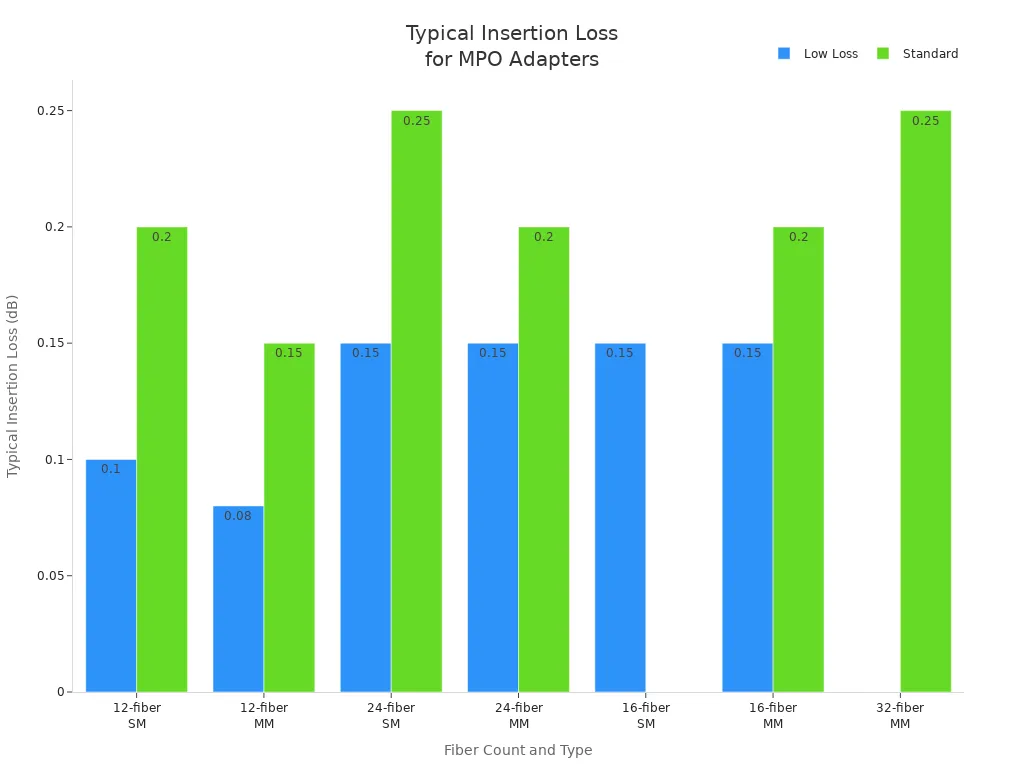
Insertion loss measures the amount of signal lost when light passes through a connector or adapter. Low-loss MPO adapters use advanced materials and precise alignment to minimize this loss, making them ideal for high-speed and long-distance networks. Standard adapters, while cost-effective, may not meet the demands of modern data centers.
- Low-loss multimode MPO connectors typically have insertion loss below 0.12 dB, with a maximum of 0.25 dB.
- Standard multimode adapters often show higher values, sometimes reaching up to 0.50 dB.
- Singlemode low-loss adapters usually maintain insertion loss around 0.10–0.15 dB, while standard versions can reach 0.70 dB or more.
| Fiber Count | Connector Type | Typical Insertion Loss Range (dB) | Maximum Insertion Loss (dB) |
|---|---|---|---|
| 12-fiber SM | Low Loss | ~0.10 | 0.25 |
| 12-fiber SM | Standard | ~0.20 | 0.70 |
| 12-fiber MM | Low Loss | ~0.08 | 0.25 |
| 12-fiber MM | Standard | ~0.15 | 0.50 |
| 24-fiber SM | Low Loss | ~0.15 | 0.35 |
| 24-fiber SM | Standard | ~0.25 | 1.00 |
Note: Choosing low-loss adapters helps maintain signal strength, especially in high-density or long-distance applications.
Impact of MPO Adapter Performance on Network Quality
The performance of an MPO Adapter directly affects network quality and reliability. Low insertion loss ensures minimal signal weakening, supporting high-speed data transmission and reducing the risk of downtime. High insertion loss, often caused by misalignment, contamination, or substandard materials, leads to signal degradation and increased maintenance costs.
- Adapters with insertion loss below 0.2 dB help maintain data integrity in demanding environments.
- High-quality adapters withstand up to 1,000 insertions without performance loss.
- Proper alignment and compatibility with fiber types prevent cumulative losses that can exceed cable loss.
- Features like dust shutters protect against contamination, preserving signal quality.
Network engineers should always test adapters in real-world scenarios to verify performance. Investing in trusted brands and low-loss options reduces failures and supports the needs of modern, high-speed networks.
MPO Adapter Equipment Interface
MPO Adapter Footprint and Mounting Style
Data centers rely on standardized MPO adapter footprints and mounting styles to ensure efficient fiber management. The most common mounting style uses rack mount fiber enclosures designed for 19-inch racks. These enclosures come in vertical footprints such as 1RU, 2RU, and 4RU, supporting a range of connection densities. Wall mount fiber enclosures offer a compact solution for installations with limited space, often positioned near cable entry points.
MPO adapters integrate into fiber optic adapter panels or patch panels within these enclosures, organizing and protecting fiber connections. Adapter plates typically accommodate 6 or 12 MPO adapters and support key-up to key-down or key-up to key-up configurations. These plates fit into standard rack mount frames, making them ideal for high-density environments. The adapters themselves come in versions such as 12-fiber flanged, flangeless, and SC footprint types, providing flexibility for different installation needs.
Note: Modular MPO adapter designs allow for easy installation and reconfiguration, which helps data centers scale quickly.
Compatibility with Patch Panels and Cassettes
Selecting the correct MPO adapter interface is essential for seamless integration with patch panels and cassettes. Patch panels designed for MPO interfaces often feature LC connectors on the front and MPO connectors on the rear. The MPO adapter must match the trunk cables and cassette interfaces to ensure proper mating and reliable performance.
Cassettes use MPO adapters on the back to accept trunk cables, while the front provides standard interfaces for equipment connections. Modular designs support specific fiber counts, such as 12 or 24 fibers, which directly impact density and cable management. Features like spreadable adapters improve connector access and reduce insertion loss, supporting efficient maintenance. Factory pre-terminated MPO components further guarantee compatibility and simplify installation, reducing the risk of field termination errors.
Tip: Always verify that the MPO adapter interface matches both the patch panel and cassette specifications to maintain optimal network performance.
MPO Adapter Cable Type Compatibility
Singlemode vs. Multimode MPO Adapter Support
Network designers must understand the differences between singlemode and multimode fiber when selecting an MPO Adapter. These adapters support both fiber types, offering flexibility for various network environments. Most MPO adapters accommodate connectors with different port counts, such as 4, 6, 8, or 12. Adjustable keyways allow technicians to change orientation for straight or cross wiring, which enhances compatibility across different systems.
- MPO adapters work with both singlemode and multimode fibers.
- They support a range of fiber counts, including 12 and 24.
- Adjustable keyways provide orientation flexibility.
Adapters designed for both singlemode and multimode fibers simplify inventory management and installation. However, mixing singlemode and multimode components can lead to performance issues, such as increased insertion loss or core size mismatches. Technicians should always match the adapter type to the fiber type for optimal results.
Note: Always verify the fiber type before installation to prevent signal loss and maintain network reliability.
OM3, OM4, OS2 MPO Adapter Considerations
Selecting the correct MPO Adapter requires careful attention to the specific fiber type in use. OM3 and OM4 represent multimode fibers, each with unique performance characteristics. OM3 cables, with their aqua-colored sheaths, support 10 Gigabit Ethernet up to 300 meters. OM4 cables extend this reach to 550 meters and enable higher speeds, such as 40 or 100 Gigabit Ethernet. Both use a 50-micrometer core, but OM4 offers greater bandwidth and future-proofing for data centers.
OS2 fibers, designed for singlemode applications, excel in long-distance transmissions with low signal loss. MPO adapters must match the fiber mode—multimode (OM3, OM4) or singlemode (OS2)—to ensure proper connectivity and maintain low insertion loss. Performance standards, including insertion loss and return loss, play a critical role in adapter selection. Matching the adapter to the cable type supports high data rates and network scalability.
| Fiber Type | Typical Use | Sheath Color | Adapter Requirement |
|---|---|---|---|
| OM3 | 10G up to 300m | Aqua | Multimode MPO |
| OM4 | 40/100G up to 550m | Aqua | Multimode MPO |
| OS2 | Long-distance, low loss | Yellow | Singlemode MPO |
Tip: Matching the MPO Adapter to the cable type ensures optimal performance and supports future network upgrades.
MPO Adapter Future-Proofing
Scalability and Upgradability with MPO Adapters
Network designers often prioritize scalability when planning for future growth. MPO adapters with high fiber count options, such as 12, 24, or even 72 fibers, allow networks to expand capacity without major infrastructure changes. Modular designs enable technicians to add or reconfigure connections quickly, supporting evolving requirements. MTP connectors, an enhanced version of MPO, offer removable housings for easier maintenance and reconfiguration. This feature reduces downtime in large-scale environments.
Key features that make an MPO adapter future-proof include:
- Support for advanced technologies like 40G, 100G, and up to 800G networks.
- Compatibility with existing infrastructure for seamless integration.
- Customizable polarity and gender options to prevent signal loss.
- Low insertion loss and high return loss to maintain signal quality.
- Robust construction with protective accessories for durability.
These characteristics help organizations accommodate increasing bandwidth demands and adapt to new network architectures without costly overhauls.
Supporting Higher Data Rates with MPO Adapter Choices
Modern data centers require adapters that support higher data rates. MPO adapters play a critical role in enabling parallel transmission for 40G, 100G, and even 400G networks. For example, MPO-12 fiber cables support multi-channel transmission, making them compatible with high-speed transceivers such as 40G QSFP+ SR4 and 100G QSFP28 SR4. Advanced MPO transceivers can reach up to 400 Gbps by using multiplexing technologies.
Selecting the right MPO adapter ensures the physical layer meets strict performance standards. Low insertion loss and precise alignment maintain signal integrity, which is essential for reliable high-speed data transmission. The modular nature of MPO-based systems allows for easy upgrades from 10G to 40G or 100G by replacing modules or adapters, not the entire cabling system. This flexibility supports rapid expansion and future-proofs the network for emerging technologies.
Verifying these 10 MPO Adapter compatibility factors helps ensure seamless integration and optimal network performance. Routine compatibility checks, such as pre-installation testing and regular inspections, reduce downtime and maintenance costs. Technicians maintain network reliability by matching connector types, cleaning assemblies, and confirming proper polarity alignment.
- Conduct regular inspections and cleaning
- Use MPO testers for performance verification
FAQ
What is the difference between MPO and MTP adapters?
MTP adapters use higher precision components and offer lower insertion loss. MPO adapters meet standard requirements. Both connect multi-fiber cables but differ in performance and durability.
Can a single MPO adapter support both singlemode and multimode fibers?
No. MPO adapters must match the fiber type. Singlemode adapters support OS2 fibers. Multimode adapters support OM3 or OM4 fibers. Mixing types causes signal loss.
How often should technicians inspect and clean MPO adapters?
Technicians should inspect and clean MPO adapters before every installation and during routine maintenance. Clean connectors prevent signal loss and network downtime.