소개
A successful 100G to 4x25G migration depends as much on the cabling design as on the switch upgrade itself. The right MPO breakout harness cable lets one high-speed port serve four 25G server links without forcing a full infrastructure replacement, but selecting it requires attention to fiber count, connector type, polarity, and transceiver compatibility. This article explains the core factors that determine whether a breakout setup will work cleanly in practice, helping you avoid mismatched components, wasted capacity, and troubleshooting delays before moving into the technical details.
MPO Breakout Harness Cable Selection Basics
Upgrading a network isn’t just about investing in faster switches; it requires optimizing the physical pathways that carry your data. In the current landscape of data center scaling, migrating from legacy architectures can feel like a complex puzzle. Fortunately, the migration path doesn’t always require ripping and replacing everything at once. One highly effective strategy is splitting high-capacity leaf switch ports to feed multiple lower-capacity server NICs.
This is precisely where a reliable MPO 브레이크 아웃 하네스 케이블 proves invaluable. It serves as the physical bridge that makes a seamless transition possible, allowing you to maximize switch port density while accommodating servers stepping up to 25G speeds.
Key terms and baseline definitions
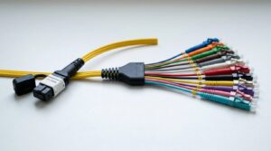
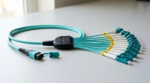
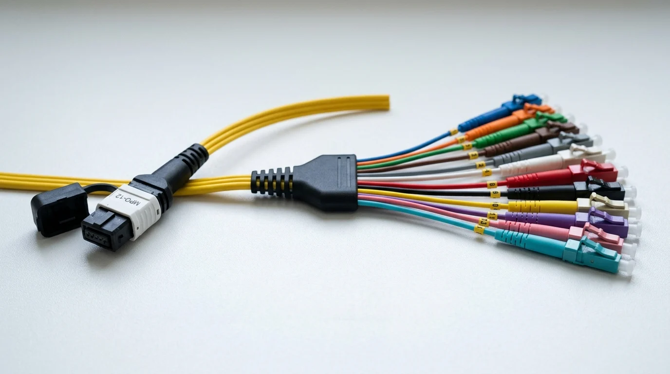
It helps to clarify terminology before diving deeper. Terms like MPO Fanout Cable 그리고 Fiber Breakout Cable are often used interchangeably by vendors and engineers. Essentially, these refer to a single high-density MPO connector on one end that physically splits into multiple duplex LC connectors on the other.
For a standard 100G connection breaking out to four 25G links, an 8-fiber configuration out of a standard 12-fiber ferrule is typically used. This setup utilizes four fibers to transmit and four to receive, leaving the middle four fibers dark. Understanding this physical layout is the first step in ensuring you don’t overpay for unused glass in your cable runs.
Why correct cable selection matters
Cable selection significantly impacts overall network health. Skimping on cabling invites bit errors and intermittent link drops. When pushing 100 Gbps of critical traffic through a single top-of-rack switch port, a mismatch in polarity or a poorly terminated connector can spike latency or drop the link entirely.
Considering that a high-end 100G transceiver can cost upwards of $500 to $800, risking its performance on a subpar cable makes little financial sense. Spending an extra 15% to 20% on a premium harness cable can prevent thousands of dollars in troubleshooting downtime when lighting up a new row of high-performance servers. The cost of a failed cable replacement is dwarfed by the cost of the outage it causes.
Specifications to Compare
With the criticality of these cables established, it is time to examine the specifications. Comparing specs isn’t just about reading a marketing datasheet; it requires precisely matching the physical layer to your specific optic transceivers to guarantee flawless data transmission.
You must also consider fiber jacket ratings—such as OFNR (Riser), OFNP (Plenum), or LSZH (Low Smoke Zero Halogen)—depending on local fire codes, but the optical performance specs remain the primary focus for network reliability.
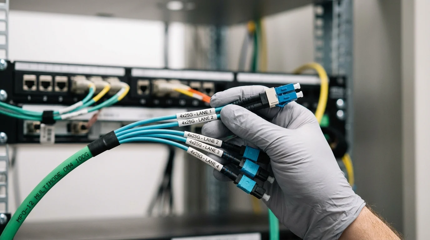
Polarity, fiber count, and connector type
The core elements of MPO spec matching are polarity, fiber count, and connector type. For a standard 100G~4x25G split, a Base-8 configuration with Type B polarity is generally required. Type B uses a key-up to key-up orientation, effectively flipping the fiber positions so that transmit signals on one end correctly route to the receive ports on the SFP28 optics at the other end.
Here is a quick breakdown of how different MPO bases compare during deployment planning:
| MPO Base Type | Total Fibers | Active Fibers (100G) | 공통 응용 |
|---|---|---|---|
| Base-8 | 8 | 8 (4 Tx / 4 Rx) | QSFP28 to 4x SFP28 |
| Base-12 | 12 | 8 (4 unused) | Legacy 40G/100G backbones |
| Base-24 | 24 | 20 (10 Tx / 10 Rx) | 100GBASE-SR10 |
Insertion loss and performance metrics
Next is insertion loss, arguably the most critical performance metric during the design phase. Every time a connection or splice is introduced into the fiber path, a portion of the light signal is lost.
For standard MPO connectors, insertion loss typically hovers around a maximum of 0.75 dB per mated pair. However, when designing a high-speed link with tight optical power budgets—especially over OM4 multimode fiber approaching its 100-meter distance limit—low-loss connectors are highly recommended. These premium connectors guarantee a maximum insertion loss of just 0.35 dB. That 0.40 dB difference might sound minor on paper, but it can be the deciding factor between a stable, clean link and one that constantly throws forward error correction (FEC) faults under heavy load.
How to Choose the Right Cable
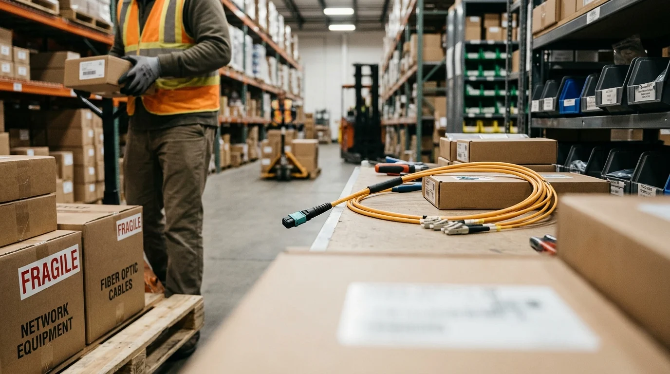
With the technical specs established, procuring the right gear for your facility is the next step. Moving from the drawing board to the purchasing phase introduces new variables that must be navigated carefully to keep projects on time and under budget.
Procurement is where theoretical network designs meet the real-world constraints of supply chains, vendor lock-in, and aggressive deployment schedules.
Practical validation steps
Before signing off on a bulk order for a major rollout, practical validation is essential. This involves acquiring a sample batch from the manufacturer and running rigorous tests with an optical time-domain reflectometer (OTDR) or a Fluke tester. Requesting 3D interferometer end-face geometry reports for every connector is also a best practice.
For multimode fiber applications, ensure the reflectance stays strictly below the -45 dB threshold. If a vendor cannot provide individual test reports showing a factory defect rate reliably under 0.1%, it is often best to look elsewhere. It is not worth the risk of introducing a microscopic piece of dirt or a scratched ferrule that could permanently damage a highly sensitive, expensive transceiver port.
Buying criteria: price, lead time, and compatibility
Balancing price, lead time, and compatibility is the final hurdle in the procurement process. Ensure that your chosen vendor can meet aggressive deployment schedules without compromising the strict compatibility requirements of your network hardware. A lower upfront price is never worth the cost if long lead times delay your project or if the cables fail to integrate seamlessly with your existing transceivers.
주요 테이크 아웃
- MPO 브레이크아웃 하네스 케이블에 대한 가장 중요한 결론과 이론적 근거
- 커밋하기 전에 검증할 가치가 있는 사양, 규정 준수 및 위험 검사
- 실용적인 다음 단계와 주의 사항은 독자가 즉시 적용할 수 있습니다.
자주 묻는 질문
What MPO breakout harness is typically used for 100G to 4x25G upgrades?
Use a QSFP28 to 4x SFP28 MPO-to-LC harness, usually Base-8 with Type B polarity, matched to your transceivers and switch breakout settings.
Why does polarity matter on an MPO breakout harness cable?
Wrong polarity can swap transmit and receive paths, causing link failures or unstable ports. Verify the harness polarity matches your optics before deployment.
Should I choose Base-8 or Base-12 for a 100G to 4x25G breakout?
Base-8 is usually the best fit because all 8 fibers are active for 4x25G. Base-12 can work, but four fibers remain unused.
What insertion loss should I look for when buying an MPO breakout harness cable?
Choose low-loss assemblies with clearly stated insertion-loss specs from a reputable supplier like Newsunn. Lower loss improves margin and helps prevent errors on high-speed links.
How do I confirm an MPO breakout harness cable will work in my data center?
Check connector type, polarity, fiber mode, length, jacket rating, and transceiver compatibility. On Newsunn product pages, compare these specs before ordering.