


소개
As edge deployments shift from centralized cores to space-constrained micro data centers, physical connectivity has a direct impact on latency, scalability, and reliability. MPO solutions address this challenge by consolidating many fibers into compact interfaces that support high-speed links without the cable congestion typical of legacy patching. That density matters at the edge, where airflow, thermal stability, and fast equipment changes can influence real-world response times as much as raw bandwidth. This article explains how advanced MPO connectivity helps reduce latency in edge environments, which design factors most affect performance, and what to consider when building cleaner, higher-capacity fiber architectures for 400G and beyond.
Why MPO connectivity matters for reducing latency at the edge
When evaluating current network architectures, pushing compute power closer to the user is no longer just a luxury—it is an absolute necessity. We are moving away from massive, centralized hubs toward highly distributed micro-sites. However, relocating high-performance servers to an Edge data center introduces severe physical space constraints and power limitations. This is exactly where MPO (Multi-Fiber Push On) connectivity becomes a game-changer, keeping latency in check while maximizing port density in tight quarters.
Business and technical drivers
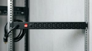
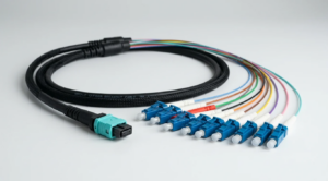
AI inference at the edge, aggressive 5G network rollouts, and autonomous IoT systems demand round-trip times well under the 5-millisecond mark. To handle massive throughput without bottlenecks, edge facilities are rapidly migrating from 10G and 40G to 400G and 800G switch fabrics. Achieving this level of port density using traditional LC duplex patching creates an unmanageable rat’s nest of cables. MPO connectors solve this by packing 12, 16, or even 24 optical fibers into a single interface roughly the size of a standard RJ45 copper jack. This extreme density reduces cable bulk, drastically improving rack airflow and cooling efficiency. Better cooling indirectly prevents the thermal throttling of optical transceivers, avoiding the sudden, unpredictable latency spikes that plague poorly designed edge nodes.
Latency factors in MPO fiber architectures
You might wonder how a passive optical connector impacts network latency. While the speed of light in fiber is a constant physical property (roughly 5 microseconds of delay per kilometer), the overall optical loss budget heavily dictates how much mathematical error correction is needed at the transceivers. Forward Error Correction (FEC) algorithms are vital for high-speed optics, but they introduce measurable latency—sometimes adding 100 to 150 nanoseconds of processing delay per hop if the signal is severely degraded. By deploying high-quality low-latency fiber paired with ultra-low insertion loss MPO trunks, pristine optical signals are maintained. Keeping total link loss safely below the strict 1.5 dB threshold required for 400GBASE-SR8 means transceivers do not have to work as hard to correct bit errors, keeping the edge compute environment incredibly fast and responsive.
How MPO solutions improve edge computing performance

Getting the absolute most out of edge computing deployments requires smart, deliberate decisions about physical optical infrastructure. Relying on any standard multi-fiber cable in a rack will not automatically solve bandwidth or delay problems. Engineers must look closely at the design choices behind these connections to truly optimize the data path.
Design choices: polarity, fiber count, and insertion loss
Three major design factors drive performance: fiber count, polarity, and insertion loss. First, fiber count is evolving. While 12-fiber MPOs have been the reliable workhorse for 40G and 100G base-8 applications, 16-fiber or even 24-fiber MPOs are recommended for future-proof 400G and 800G deployments. Specifically, next-generation 400G SR8 transceivers require a 16-fiber interface to function. Next is polarity, which dictates how transmit and receive signals align. Method B (key-up to key-up) is generally preferred for its straightforward simplicity in maintaining proper transmit-to-receive mapping without requiring complex cassette flips. Finally, when breaking out massive high-speed switch ports to multiple lower-speed edge servers, utilizing a premium MPO fanout cable with an insertion loss strictly capped at 0.35 dB per mated pair is crucial for maintaining overall signal health and minimizing bit error rates.
How to compare MPO options
When evaluating options for compact connectivity, the manufacturer’s spec sheet is an essential tool. Standard MPO connectors are perfectly fine for short, simple runs in enterprise closets, but edge computing environments often require “Low-Loss” or “Elite” variants to stay within tight optical budgets. Here is a quick breakdown for comparing MPO component grades in edge deployments:
| MPO Grade | 최대 삽입 손실(dB) | 전형적인 IL (DB) | Min Return Loss (dB) | Best Edge Use Case |
|---|---|---|---|---|
| 표준 손실 | 0.75 | 0.50 | 20 | Legacy 10G/40G edge nodes with generous loss budgets |
| Low-Loss (Elite) | 0.35 | 0.20 | 20 | 100G/400G short reach connections within the same row |
| Ultra-Low Loss | 0.25 | 0.10 | 25 | 800G interconnects and strict FEC latency budgets |
By selecting the ultra-low loss tier, network architects gain valuable headroom for additional patching without triggering latency-inducing signal regeneration.
How to select, deploy, and scale MPO for low-latency networks
Knowing the technical specifications is only half the battle when building out an edge node. Getting these dense cables into edge cabinets and scaling them seamlessly as the user base grows takes a highly tactical approach. Proper physical deployment and vendor selection ensure the network stays lightning-fast and highly reliable from day one.
Deployment steps to reduce risk
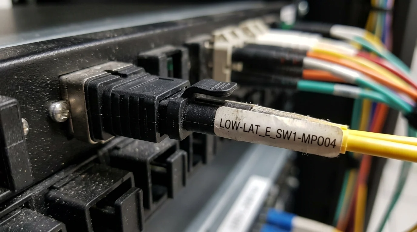
It is critical to inspect and clean every single MPO end-face before mating it. Because an MPO connector houses multiple delicate fibers within a single polymer ferrule, a microscopic speck of dust or skin oil can hold the entire connector slightly apart. This ruins the signal integrity across all 12 or 16 optical channels simultaneously. Industry studies consistently show that end-face contamination causes over 85% of fiber network failures and performance degradation. Always use a dedicated one-click MPO cleaner and a digital inspection probe before making a connection. Once cleaned, route the trunks using proper bend-radius managers. Exceeding the typical 20mm minimum bend radius on standard micro-core cables induces macro-bending losses, which directly hurts the carefully planned latency budget.
Selection criteria: cost, interoperability, and compliance
When selecting an MPO vendor for an edge rollout, do not just shop based on the lowest price tag. It is equally important to evaluate interoperability with existing transceivers and ensure strict compliance with industry standards to guarantee long-term performance and reliability.
주요 테이크 아웃
- The most important conclusions and rationale for MPO
- 커밋하기 전에 검증할 가치가 있는 사양, 규정 준수 및 위험 검사
- 실용적인 다음 단계와 주의 사항은 독자가 즉시 적용할 수 있습니다.
자주 묻는 질문
Why is MPO preferred over LC in edge data centers?
MPO packs 12, 16, or 24 fibers into one compact connector, reducing cable bulk and improving airflow. That helps dense edge racks support 400G/800G links with fewer cooling-related latency spikes.
How can MPO connectivity help reduce latency?
MPO itself is passive, but low-loss MPO links preserve signal quality. With lower insertion loss, transceivers need less FEC correction, which can cut added per-hop processing delay in high-speed edge links.
Which MPO fiber count is best for 400G edge deployments?
For 400G SR8, use 16-fiber MPO. For older 40G/100G base-8 designs, 12-fiber MPO is common, but 16-fiber or 24-fiber options are better for future-ready edge upgrades.
What insertion loss should I look for in MPO components?
For edge 100G/400G links, target low-loss MPO with about 0.35 dB max per mated pair. For tighter 800G budgets, ultra-low-loss options around 0.25 dB are safer.
Where can I compare MPO products for edge applications on Newsunn?
Start with the product and specification resources at newsunn.com. Check MPO trunk, fanout, and low-loss options, then confirm fiber count, polarity, and insertion-loss ratings against your target speed.